Supercharge Your Innovation With Domain-Expert AI Agents!

A rotary flapping wing aircraft

A flapping-wing aircraft and left-rotating technology, applied in the field of aircraft, can solve the problems of poor maneuverability, low efficiency, and high fatigue strength requirements of flapping wings, and achieve the effect of strong maneuverability and flexible control

Active Publication Date: 2015-12-30
广州欣彩电脑耗材有限公司
View PDF6 Cites 0 Cited by
  • Summary
  • Abstract
  • Description
  • Claims
  • Application Information

AI Technical Summary

Problems solved by technology

[0002] The lift device used in the traditional flapping wing aircraft is the traditional flapping wing mechanism, which is driven by the crankshaft and connecting rod. The flapping wing flaps up and down to generate lift. The efficiency is low. Lift, it is difficult to vertically lift and hover in the air, and the maneuverability is poor

Method used


Image

  • A rotary flapping wing aircraft
  • A rotary flapping wing aircraft

Examples


Embodiment Construction

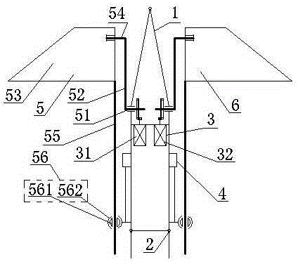
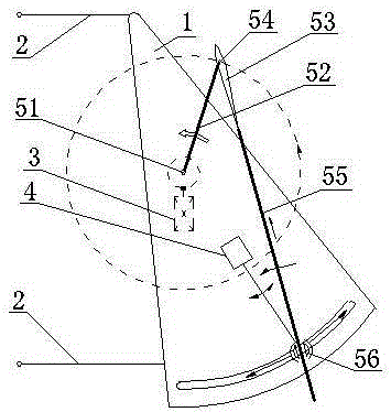
[0013] now attached figure 1 And attached figure 2 The present invention is described with an example: a rotary flapping wing aircraft includes a fuselage 1 , a landing gear 2 , a power system 3 and a control system 4 . Power system 3 includes left engine 31 and its speed regulating device, right engine 32 and its speed regulating device, left rotating flapping wing 5 and right rotating flapping wing 6; control system 4 includes engine control system and flight attitude control system; The wing 5 and the right-rotating flapping wing 6 have the same structure, and they are respectively symmetrically arranged on the left and right sides of the fuselage 1. The left-rotating flapping wing 5 is driven by the left engine 31, and the right-rotating flapping wing 6 is driven by the right engine 32; the left engine 31 and the Right motor 32 structures and parameters are all identical, and their gear reducer and speed regulating device are also identical. The aircraft can lift and ho...


PUM


Abstract

The invention provides a rotary ornithopter, belonging to the technical field of air vehicles. The ornithopter comprises a body, undercarriages, a power system and a control system, wherein the power system comprises two same engines and gear reducers and speed adjusting devices thereof, a left rotary flapping wing and a right rotary flapping wing; the control system comprises an engine control system and a flight attitude control system; the left rotary flapping wing comprises a left main shaft, a left rotary arm, a left vane, a left wing shaft, a left guide rod and a left guider; the right rotary flapping wing comprises a right main shaft, a right rotary arm, a right vane, a right wing shaft, a right guide rod and a right guider; the left and right rotary flapping wings have the same structure, are respectively arranged on the left and right sides of the body symmetrically and are respectively driven by the two same engines independently. The ornithopter can ascend and descend vertically and hover and is flexible. With shooting equipment, the ornithopter can be used in various tasks such as air photography, geographic survey, traffic duty, military surveillance, rescue and relief work and the like.

Description

technical field [0001] A rotary flapping-wing aircraft belongs to the field of aircraft technology, and in particular relates to a flapping-wing aircraft. Background technique [0002] The lift device used in the traditional flapping wing aircraft is the traditional flapping wing mechanism, which is driven by the crankshaft and connecting rod. The flapping wing flaps up and down to generate lift. The efficiency is low. Lift, it is difficult to lift vertically and hover in the air, and the maneuverability is poor. Contents of the invention [0003] In order to overcome the deficiencies of the above-mentioned traditional aircraft, the present invention provides a rotary flapping-wing aircraft. The flapping wings perform rotary motion, can be vertically lifted and hovered, and the left and right flapping wings are independently driven and controlled, and the maneuverability is strong. [0004] The present invention adopts the following technical solutions: a rotary flapping ...

Claims


Application Information

Patent Timeline
Patent Type & Authority Patents(China)
IPC IPC(8): B64C33/02B64C33/00
Inventor 王志成
Owner 广州欣彩电脑耗材有限公司
Features
  • R&D
  • Intellectual Property
  • Life Sciences
  • Materials
  • Tech Scout
  • Unparalleled Data Quality
  • Higher Quality Content
  • 60% Fewer Hallucinations
Learn More