Mining lifting machine

A technology for elevators and mines, which is applied in the direction of lifting devices, etc., can solve the problems of safety, hidden dangers, and ladders that cannot adapt to the environment, etc., and achieve the effects of safe and convenient use, increased safety, and saved working time and labor costs

Inactive Publication Date: 2014-08-20
SHANXI DONGHUA MACHINERY
View PDF5 Cites 7 Cited by
  • Summary
  • Abstract
  • Description
  • Claims
  • Application Information

AI Technical Summary

Problems solved by technology

[0002] Workers do drilling at high places or work for a long time without a relatively stable, safe and comfortable environment. When climbing high with ladders, the legs and feet are uncomfortable placed in the ladder bars. If the time is too long, it will cause fatigue. If the lower part is unstable, there will be safety hazards if the climbing operation is carried out in a place with a relatively harsh environment, and the ladder may not be able to adapt to the environment for climbing operations

Method used


Image

  • Mining lifting machine
  • Mining lifting machine
  • Mining lifting machine

Examples


Embodiment 1

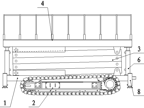
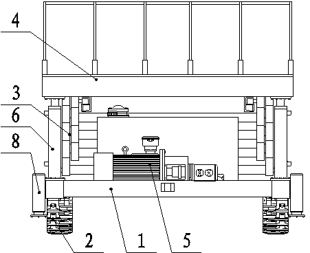
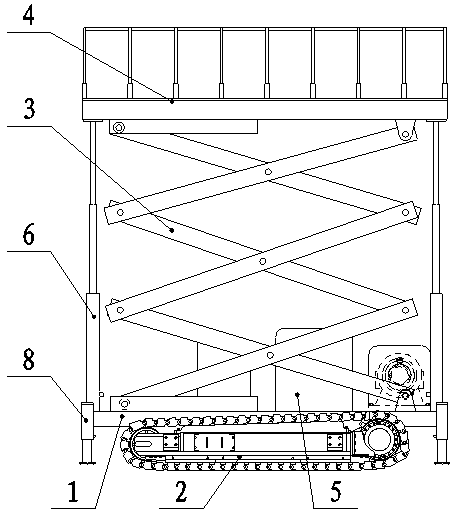
[0027] Such as Figure 1-3 , Figure 7 As shown, the mining elevator includes a frame 1, a running part 2, an elevator 3, a platform 4, a pump station 5 and a telescopic oil cylinder 6, and a running part 2 is installed on the lower part of the frame 1, and the running part 2 is a crawler walking mechanism. , the frame 1 and the platform 4 are connected together by two elevators 3, the structure of the elevators 3 is that a plurality of connecting rods are hinged to form a telescopic connected rhombus frame, and the ends of the two connecting rods at the lower end of the elevators 3 It is hinged with the frame 1, and the two connecting rod ends at the upper end of the elevator 3 are hinged with the bottom surface of the platform 4. A pump station 5 is installed on the frame 1 between the two elevators 3. The four ends of the frame 1 The corners are connected to four corresponding end corners of the platform 4 through a telescopic oil cylinder 6 , and the telescopic oil cylind...

Embodiment 2

[0033] Such as Figure 4-7 As shown, the mining elevator includes a frame 1, a running part 2, an elevator 3, a platform 4, a pump station 5 and a telescopic oil cylinder 6, and the bottom part of the frame 1 is equipped with a running part 2, and the running part 2 is a solid tire. Frame 1 and platform 4 are connected together by two elevators 3, and the structure of described elevators 3 is that a plurality of connecting rods are hinged into a telescopic connected rhombus frame, and the two connecting rod ends at the lower end of elevators 3 are connected to The frame 1 is hinged, the two connecting rod ends at the upper end of the elevator 3 are hinged with the bottom surface of the platform 4, and the pump station 5 is installed on the frame 1 between the two elevators 3, and the four end corners of the frame 1 The four corresponding end angles of the platform 4 are all connected through a telescopic oil cylinder 6 , and the telescopic oil cylinder 6 is powered by the pump...


PUM


Abstract

The invention belongs to the technical field of auxiliary devices for high-position installation, and relates to a mining lifting machine to achieve the technical purpose of providing the mining lifting machine favorable for high position installation. The mining lifting machine is simple in structure and safe and convenient to use. According to the technical scheme, the mining lifting machine comprises a machine frame, a walking part, elevators, a platform, a pump station and telescopic oil cylinders. The lower portion of the machine frame is provided with the walking part, the machine frame is connected with the platform through the two elevators, the elevators are of structures that a plurality of connecting rods are hinged into retractable connected rhombus frameworks, the ends of the two connecting rods at the lower ends of the elevators are hinged to the machine frame, the ends of the two connecting rods at the upper ends of the elevators are hinged to the bottom face of the platform, the part, between the two elevators, of the machine frame is provided with the pump station, and the four end corners of the machine frame are connected with the four corresponding end corners of the platform through the telescopic oil cylinders with the power supplied by the pump station. The mining lifting machine is mainly used for helping workers to carry out the high-position operation in a roadway.

Description

technical field [0001] The mine elevator of the invention belongs to the technical field of high-level installation auxiliary equipment. Background technique [0002] Workers do drilling at high places or work for a long time without a relatively stable, safe and comfortable environment. When climbing high with ladders, the legs and feet are uncomfortable placed in the ladder bars. If the time is too long, it will cause fatigue. If the lower part is unstable, there will be safety hazards if the climbing operation is performed in a place with a relatively harsh environment, and the ladder may not even be able to adapt to the environment for climbing operations. Contents of the invention [0003] The invention overcomes the deficiencies in the prior art, and the technical problem to be solved is to provide a mine lift that is easy to install at a high position, has a simple structure, and is convenient and safe to use. [0004] In order to solve the above-mentioned technica...

Claims


Application Information

Patent Timeline
Patent Type & Authority Applications(China)
IPC IPC(8): B66F11/04B66F13/00
Inventor 慎志东贾金龙宋翠萍王亚亮张晓芳
Owner SHANXI DONGHUA MACHINERY
Why Eureka
Try Eureka