Lifting device

A lifting device and lifting frame technology, applied in the direction of lifting device, elevator, lifting frame, etc., can solve the problem of high requirements for lateral stability of the lifting frame of the lifting component, high requirements for holding accuracy and transmission control accuracy, and high lifting requirements. problems such as lateral stability and stiffness fluctuation, to achieve the effect of good longitudinal and lateral stability, good synchronization, and strong environmental test ability

Pending Publication Date: 2022-05-13
四川中陆嘉诚科技有限公司
View PDF7 Cites 2 Cited by
  • Summary
  • Abstract
  • Description
  • Claims
  • Application Information

AI Technical Summary

Problems solved by technology

[0003] However, in the process of using the prior art, the inventors found that there are at least the following problems in the prior art: when the hydraulic cylinder is subject to a certain impact force, the hydraulic oil will be slightly compressed, thus unable to provide sufficient rigidity to meet the requirements of the spring on the vehicle. Requirements for maintaining high-precision positioning of boxes and other devices
At the same time, the response speed of the control of the hydraulic cylinder is slow and the control accuracy is poor; and the hydraulic oil of the hydraulic drive system also has a certain impact on environmental pollution; have a certain influence on the control
In addition, when the dual hydraulic cylinders are used for lifting, sometimes the position of the center of mass of the lifting body is constantly changing, resulting in certain fluctuations in the lateral stability and stiffness of the lifting. However, the working environment of special vehicles varies widely, and the impact on the ammunition box The maintenance accuracy of the lifting height and the transmission control accuracy are high, and the motion response should be fast, and the rigidity of the lifting component and the lateral stability of the lifting frame are high.

Method used


Image

  • Lifting device
  • Lifting device
  • Lifting device

Examples


Embodiment 1

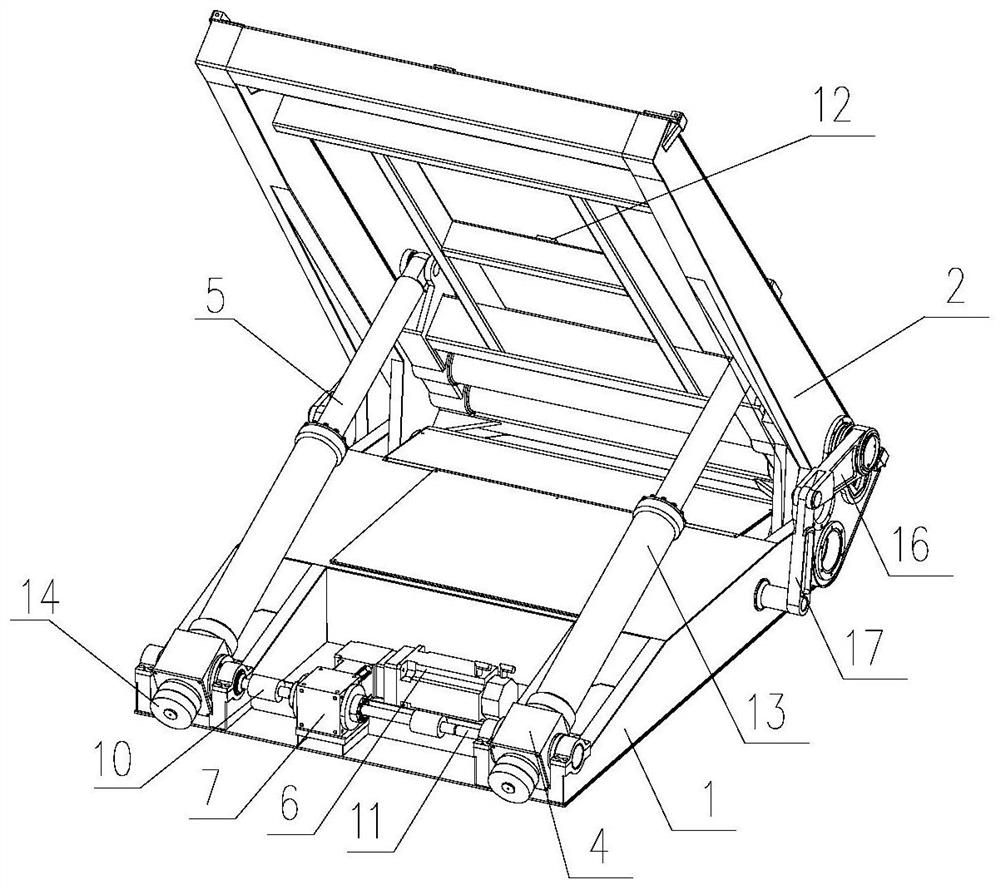
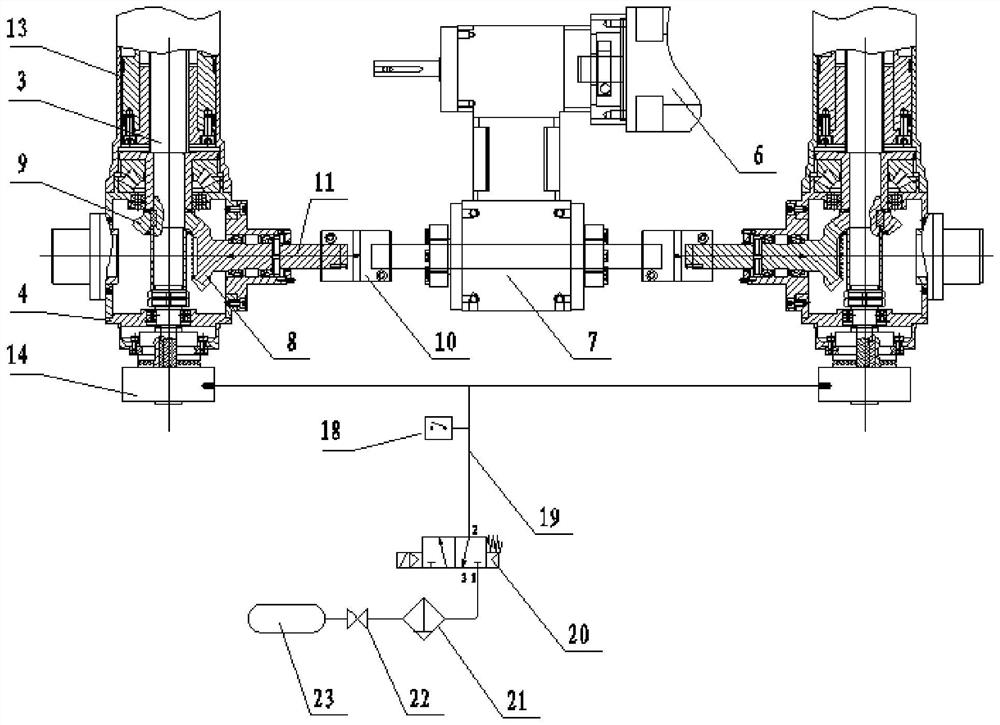
[0025] This embodiment provides a lifting device, such as figure 1 As shown, it includes a base 1, a lifting frame 2, a lifting assembly and a driving assembly; the lifting frame 2 is rotatably connected to the base 1; one end of the lifting assembly is rotatably connected to the lifting frame 2, and the other One end is rotationally connected with the end of the base 1 away from the lifting frame 2; the driving assembly is arranged on the base 1, and the driving assembly is arranged away from the lifting frame 2, and the driving assembly is used to drive the elevating assembly to elongate or shorten; The lifting assembly includes a ball screw pair 3, a positioning sleeve 4 and a support rod 5, the positioning sleeve 4 is sleeved on the end of the screw of the ball screw pair 3, the positioning sleeve 4 is connected to the base 1 in rotation, the One end of the support rod 5 is rotatably connected with the lifting frame 2, and the other end of the support rod 5 is connected wi...


PUM


Abstract

The invention relates to the technical field of vehicle auxiliary instruments, and aims to provide a lifting device. According to the technical scheme, the lifting device comprises a base, a lifting frame, a lifting assembly and a driving assembly; the lifting frame is rotationally connected with the base; one end of the lifting assembly is rotationally connected with the lifting frame, and the other end of the lifting assembly is rotationally connected with the end, away from the lifting frame, of the base. The driving assembly is arranged on the base and used for driving the lifting assembly to stretch or retract. The lifting assembly comprises a ball screw pair, a positioning sleeve and a supporting rod, the end of a screw of the ball screw pair is sleeved with the positioning sleeve, the positioning sleeve is rotationally connected with the base, one end of the supporting rod is rotationally connected with the lifting frame, and the other end of the supporting rod is connected with a nut of the ball screw pair; the driving assembly comprises a servo motor, and the output end of the servo motor is in transmission connection with a screw of the ball screw pair. The device is high in positioning precision, fast in motion response, small in transmission gap, compact in structure and applicable to special vehicles.

Description

technical field [0001] The invention relates to the technical field of vehicle auxiliary equipment, in particular to a lifting device. Background technique [0002] At present, during the use of special vehicles, many vehicles are equipped with lifting devices to lift the ammunition boxes and other devices on the vehicles. In the prior art, such as the dump truck lifting device disclosed in the Chinese patent with publication number CN102555877A, the lifting frame of the lifting device is mainly driven by a hydraulic cylinder. [0003] However, in the process of using the prior art, the inventors found that there are at least the following problems in the prior art: when the hydraulic cylinder is subject to a certain impact force, the hydraulic oil will be slightly compressed, thus unable to provide sufficient rigidity to meet the requirements of the spring on the vehicle. Boxes and other devices maintain high-precision positioning requirements. At the same time, the respo...

Claims


Application Information

Patent Timeline
Patent Type & Authority Applications(China)
IPC IPC(8): B66B7/08B66F7/22B66F7/28
CPCB66B7/085B66F7/22B66F7/28
Inventor 王敏蔡晓娟吴杰补聪
Owner 四川中陆嘉诚科技有限公司
Why Eureka
Try Eureka