Virtual reality virtual theater system

a virtual reality and theater technology, applied in the field of virtual reality virtual theater systems, can solve the problems of increasing the complexity of 3d models, long latency of existing systems, and inability to measure changes in user position and orientation, etc., and achieves the effects of reducing latency display updates, efficient rerendering, and fast performan

Inactive Publication Date: 2016-07-19
LI ADAM
View PDF4 Cites 134 Cited by
  • Summary
  • Abstract
  • Description
  • Claims
  • Application Information

AI Technical Summary

Benefits of technology

[0013]In addition, one or more embodiments of the system include an image warper. The image warper is the system component that provides for low-latency virtual reality display via efficient rerendering of scenes. The image warper may for example monitor the pose changes of the user and rerender displayed images based on these pose changes. The rerendering performed by the image warper may be a rerendering approximation, rather than a full perspective projection from the original 3D scene model. For example, some embodiments perform rerendering approximations by warping display images in relatively simple ways to partially reflect the changes in the user's pose. These rerendering approximations may offer lower latency display updates, although in some embodiments they may not be fully realistic compared to the full rendering process.
[0014]One or more embodiments of the system perform approximate rerendering by calculating a pixel translation vector, and then translating pixels of the display by this pixel translation vector. Effectively the image warper in these embodiments may shift pixels in a calculated direction and by a calculated amount to approximate the effect of the user's movements on the display. This approximation is not full 3D rendering, but it can be performed very quickly in some embodiments, greatly reducing latency between user's movements and display updates.
[0015]One or more embodiments of the system may use hardware acceleration to modify the pixels of a display to perform approximate rerendering. For example, display hardware or graphics processing unit hardware may support commands to directly shift pixels based on a pixel translation vector. Implementing pixel translations or other approximate rerendering transformations in hardware may further reduce latency in one or more embodiments.
[0016]In one or more embodiments, the rerendering approximations performed by the image warper may only be performed if the pose changes of a user are below a particular threshold value. For large changes in pose, the approximations used by the image warper may become inadequate, and it may be preferable to perform a full 3D rendering despite the high latency. For small changes in pose, the rerendering approximations may be sufficiently realistic.
[0017]In one or more embodiments, multiple pose changes for a user may be received while a full 3D rendering process is executed. By the time the 3D rendering process has completed, the initial user pose that was used for the rendering may be out of date, since newer pose data is by then available. One or more embodiments may perform a post-rendering correction on the rendered images, using the image warper to apply updates to the rendered images prior to displaying them. These post-rendering corrections may improve synchronization between the displayed images and the user's current pose.
[0018]One or more embodiments of the system may use pose prediction to calculate or estimate the pose of a user at a future time when the rendering and display processes are complete. Pose prediction may reduce the apparent latency between changes in user pose and corresponding display updates. One or more embodiments may use pose prediction for full rendering, for image warping, or for both. Embodiments may use any desired technique for pose prediction, including for example simple extrapolation of pose changes. With pose prediction, the predicted pose is provided to the rendering or approximate rerendering processes, rather than the measured pose. The rendering process calculates virtual camera poses from the predicted pose values, and renders a scene based on these virtual camera poses. The image warper calculates pose changes using the difference between the predicted future pose and the previously calculated virtual camera pose from full rendering of the scene.

Problems solved by technology

A major challenge for existing virtual reality systems is combining realistic images with low-latency rendering, so that user's virtual reality experience matches the rapid feedback to movement observed in real environments.
Existing systems often have long latency to measure changes in the user's position and orientation, and to rerender the virtual world based on these changes.
3D rendering is a complex and processor intensive operation that can take potentially hundreds of milliseconds.
Three technology trends are compounding this challenge: (1) The complexity of 3D models is growing as more 3D data is captured and generated.
As a result of these trends, high latency in rendering virtual reality displays has become a major factor limiting adoption and applications of virtual reality technology.
There are no known systems that provide sufficiently low-latency rendering and display to generate highly responsive virtual reality environments given these technology constraints.
However, an immense amount of recorded video content exists and continues to be generated that is designed for viewing on a traditional screen with a fixed and limited field of view.
While it is possible to use a virtual reality system as a video player to view this traditional content, this approach offers little advantage compared to viewing the content on a non-virtual reality screen.
There are no known systems that combine the advantages of a virtual reality environment with traditional video content to provide an immersive viewing experience for this content.
In particular, there are no known systems that embed traditional video into a virtual world in order to enhance the user's viewing experience.

Method used


Image

  • Virtual reality virtual theater system
  • Virtual reality virtual theater system
  • Virtual reality virtual theater system

Examples


Embodiment Construction

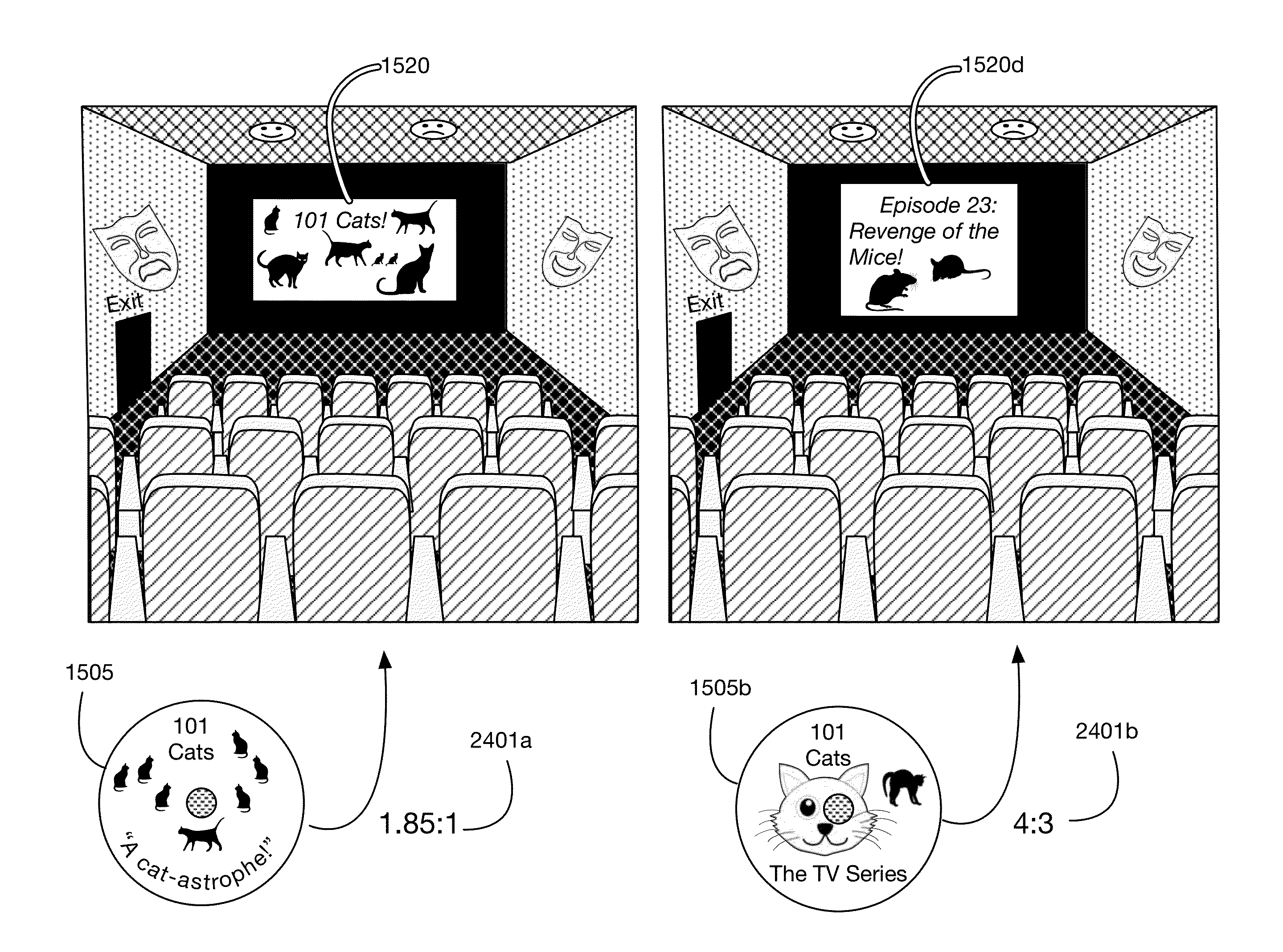
[0062]A virtual reality virtual theater system that generates or otherwise displays a virtual theater, for example in which to view videos, such as movies or television will now be described. In the following exemplary description numerous specific details are set forth in order to provide a more thorough understanding of embodiments of the invention. It will be apparent, however, to an artisan of ordinary skill that the present invention may be practiced without incorporating all aspects of the specific details described herein. In other instances, specific features, quantities, or measurements well known to those of ordinary skill in the art have not been described in detail so as not to obscure the invention. Readers should note that although examples of the invention are set forth herein, the claims, and the full scope of any equivalents, are what define the metes and bounds of the invention.

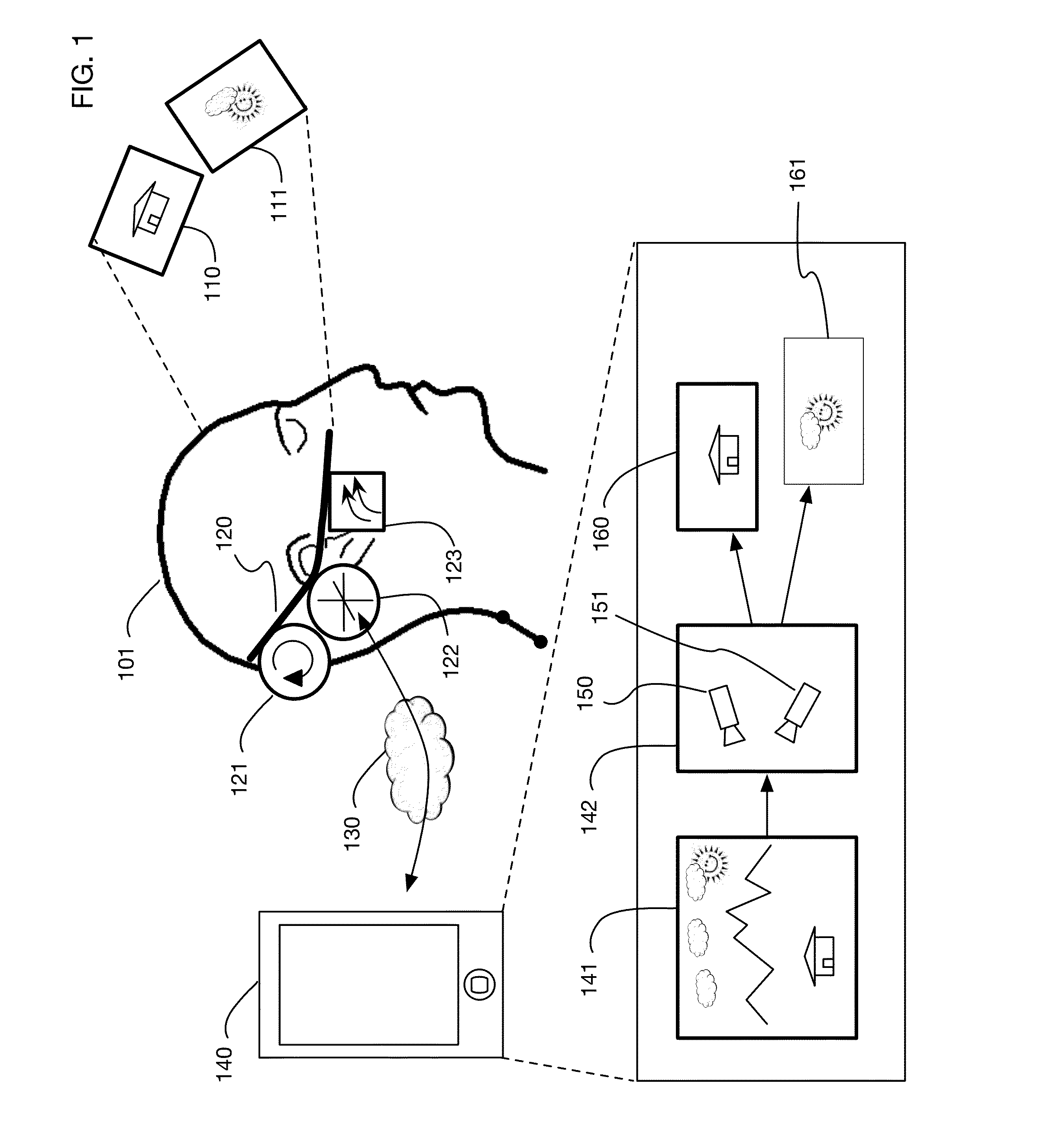
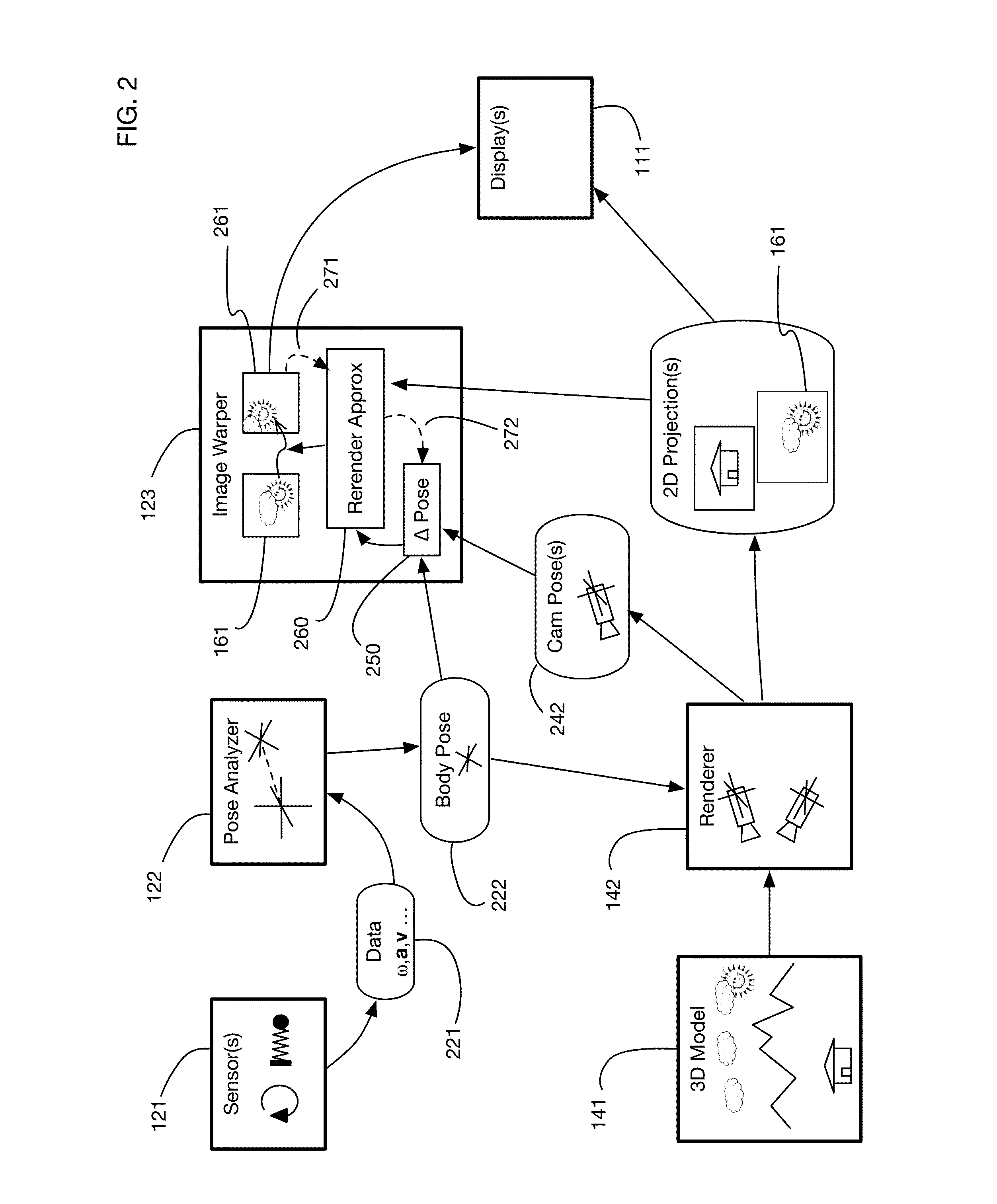
[0063]FIG. 1 shows a high-level schematic diagram of an embodiment of the invention that...


PUM


Abstract

A virtual reality virtual theater system that generates or otherwise displays a virtual theater, for example in which to view videos, such as movies or television. Videos may be for example 2D or 3D movies or television programs. Embodiments create a virtual theater environment with elements that provide a theater-like viewing experience to the user. Virtual theaters may be for example indoor movie theaters, drive-in movie theaters, or home movie theaters. Virtual theater elements may include for example theater fixtures, décor, and audience members; these elements may be selectable or customizable by the user. One or more embodiments also render sound by placing virtual speakers in a virtual theater and projecting sounds from these virtual speakers onto virtual microphones corresponding to the position and orientation of the user's ears. Embodiments may also employ minimal latency processing to improve the theater experience.

Description

[0001]This application is a continuation in part of U.S. Utility patent application Ser. No. 14 / 788,633 filed Jun. 30, 2015, the specification of which is hereby incorporated herein by reference.BACKGROUND OF THE INVENTION[0002]1. Field of the Invention[0003]One or more embodiments of the invention are related to the field of virtual reality systems. More particularly, but not by way of limitation, one or more embodiments of the invention enable a virtual reality virtual theater system that generates or otherwise displays a virtual theater, for example in which to view videos, such as movies or television. In addition, embodiments may also employ minimal latency processing to improve the theater experience.[0004]2. Description of the Related Art[0005]Virtual reality systems are known in the art. Such systems generate a virtual world for a user that responds to the user's movements. Examples include various types of virtual reality headsets and goggles worn by a user, as well as spec...

Claims


Application Information

Patent Timeline
Patent Type & Authority Patents(United States)
IPC IPC(8): G06T19/00G06T15/00G06T3/00
CPCG06T19/003G06T15/00G06T19/006G06T3/0093G06T2215/12G06T2210/61G06F3/011G02B27/017G02B2027/0134G02B2027/014G02B2027/0187H04S7/304
Inventor LI, ADAM
Owner LI ADAM
Why Eureka
Try Eureka