
Straight tube pulp molding packaging setting device

A pulp molding and setting device technology, applied in the direction of textiles and papermaking, can solve the problems of low heating efficiency and difficulty in ejecting the mold, and achieve the effects of prolonging the service life, shortening the drying time, and shortening the heating time

Active Publication Date: 2016-01-13
曲士彬
View PDF7 Cites 0 Cited by
  • Summary
  • Abstract
  • Description
  • Claims
  • Application Information

AI Technical Summary

Problems solved by technology

[0003] In order to solve the problems of low heating efficiency and difficulty in ejection of the existing straight tube pulp molding packaging setting device, the present invention further provides a straight tube pulp molding packaging setting device

Method used


Image

  • Straight tube pulp molding packaging setting device
  • Straight tube pulp molding packaging setting device
  • Straight tube pulp molding packaging setting device

Examples


specific Embodiment approach 1

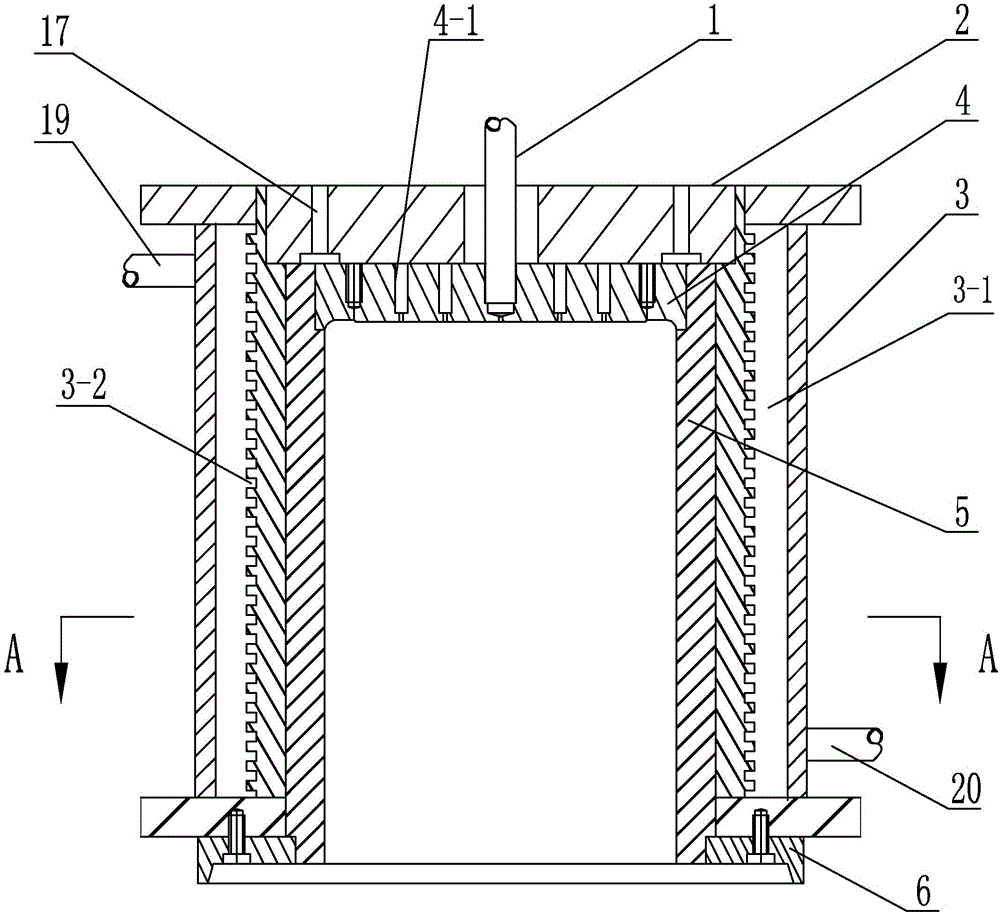
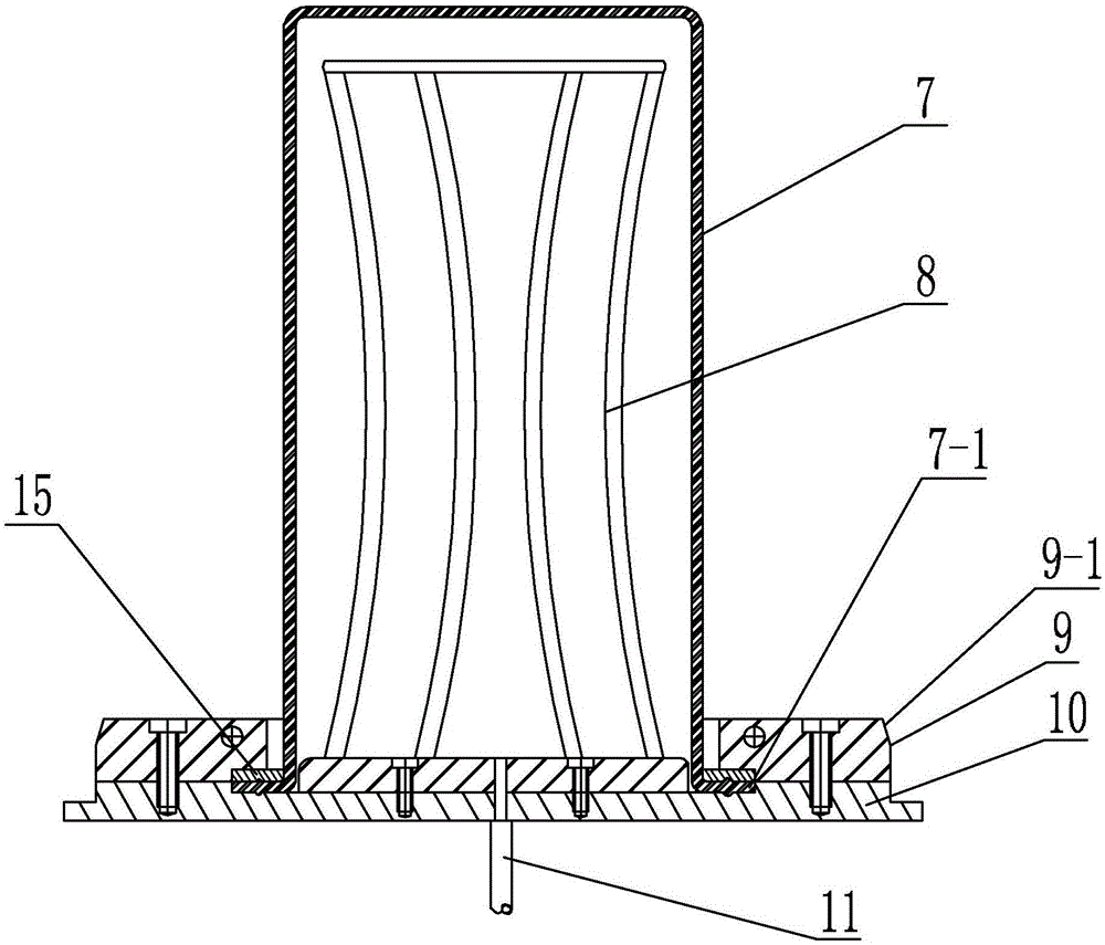
[0012] Specific implementation mode one: as Figure 1~4 As shown, the straight tube type pulp molding packaging shaping device of this embodiment includes an upper mold and a lower mold, the lower mold is located in the upper mold and the two are coaxially arranged; 3, bottom mold 4, mold cylinder 5 and positioning ring 6, heat conduction oil heater 3 is set on the outer wall of mold cylinder 5, heat conduction oil heater 3 is provided with annular heat conduction oil cavity 3-1 along the circumferential direction, close to the mold The wall surface of the heat-conducting oil chamber 3-1 of the cylinder 5 is provided with several annular grooves 3-2 in sequence from top to bottom. The upper part is provided with a heat transfer oil outlet 19; the bottom mold 4 is installed on the upper end of the mold cylinder 5, the upper end cover 2 is arranged on the upper end surface of the bottom mold 4, the positioning ring 6 is fixedly sleeved on the lower end of the mold cylinder 5, an...

specific Embodiment approach 2

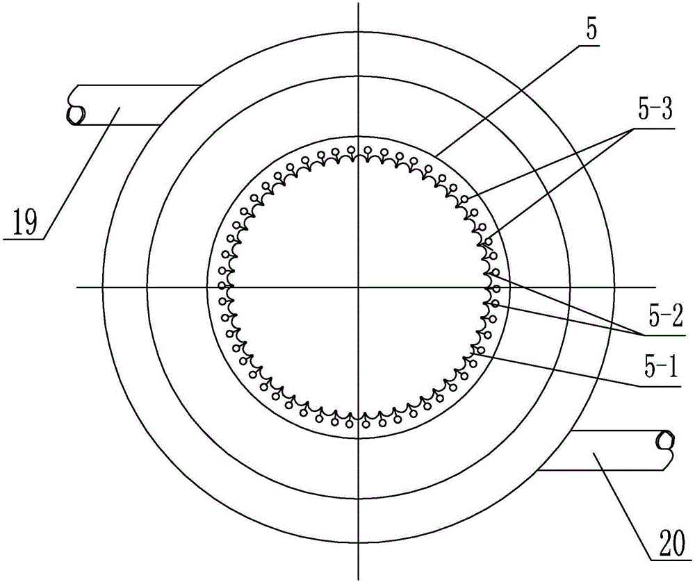
[0014] Specific implementation mode two: as image 3 As shown, the inner wall of the mold cylinder 5 in this embodiment is processed with several vertical arc-shaped grooves 5-1 along the circumferential direction. Such setting, compared with the existing smooth surface, greatly increases the compressive strength of the surface of the molded product. Other components and connections are the same as those in the first embodiment.

specific Embodiment approach 3

[0015] Specific implementation mode three: as image 3 As shown, in this embodiment, a slit 5-2 is provided along the vertical direction at the junction of two adjacent vertical arc-shaped grooves 5-1, and several vertical exhaust vents are processed on the mold barrel 5 along the circumferential direction. Holes 5-3, the number of slits 5-2 are set in accordance with the number of vertical exhaust through holes 5-3, each slit 5-2 communicates with a corresponding vertical exhaust through hole 5-3, each The upper ends of each vertical exhaust through-hole 5-3 are communicated with the second exhaust through-hole 17. This design facilitates the water vapor generated during the production of pulp molded products to be discharged through the slit 5-2, the vertical exhaust through hole 5-3, and the second exhaust through hole 17 in time. Other components and connections are the same as those in the second embodiment.


PUM


Abstract

The invention provides a cylinder type molded pulp package sizing device and relates to a molded pulp packing sizing device. The cylinder type molded pulp packing sizing device aims to solve the problems that an existing cylinder type molded pulp packing sizing device is low in heating efficiency and difficult to demold. A plurality of ring grooves are formed in the wall face of a heat conductive oil cavity close to a mold cylinder from top to bottom in sequence, a bottom mold is mounted at the upper end of the mold cylinder, an upper end cover is arranged on the upper end face of the bottom mold, a locating ring is fixedly arranged at the lower end of the mold cylinder in a sleeved mode, multiple rings of first exhaust through holes are formed in the bottom mold in the circumferential direction, multiple rings of ring grooves are formed in the upper end face of the bottom mold in the circumferential direction, each ring groove is communicated with the through holes of the corresponding ring, a plurality of exhaust grooves are formed in the upper end face of the bottom mold in the radial direction, a plurality of second exhaust through holes are formed in the upper end cover, the first exhaust through holes are communicated with the second exhaust through holes through the ring grooves and the exhaust grooves, and an outer edge is arranged at the lower end of the bottom mold in the circumferential direction. The cylinder type molded pulp package sizing device is used for manufacturing molded pulp packages.

Description

technical field [0001] The invention relates to a pulp molding packaging shaping device, in particular to a straight tube pulp molding packaging shaping device. Background technique [0002] The pulp molding industry in my country has developed rapidly, especially in recent years, the production of pulp molding has developed from products with a certain inclination such as plates, bowls, and dishes to straight products, but the existing straight pulp molding packaging is finalized The device adopts spiral coil heating, which has low heating efficiency and difficulty in ejecting the mold, which leads to low production efficiency and poor product quality of straight cylinder pulp molded packaging products, making it impossible to form large-scale production. Contents of the invention [0003] The invention aims to solve the problems of low heating efficiency and difficulty in ejecting the existing straight tube pulp molding packaging setting device, and further provides a str...

Claims


Application Information

Patent Timeline
Patent Type & Authority Patents(China)
IPC IPC(8): D21J3/00
Inventor 曲士彬
Owner 曲士彬
Learn More