Rectifier circuit and power source circuit

A technology of rectifier circuit and main electrode, which is applied in the direction of electric light source, electroluminescence light source, high-efficiency power electronic conversion, etc., and can solve the problems of conduction delay and so on

CN103997193AInactive Publication Date: 2014-08-20TOSHIBA LIGHTING & TECH CORP
1 Cites 7 Cited by

Patent Information

Authority / Receiving Office
CN · China
Patent Type
Applications(China)
Current Assignee / Owner
Publication Date
2014-08-20
Estimated Expiration
Not applicable · inactive patent

Smart Images

  • Figure 1
    Figure 1
  • Figure 2
    Figure 2
  • Figure 3
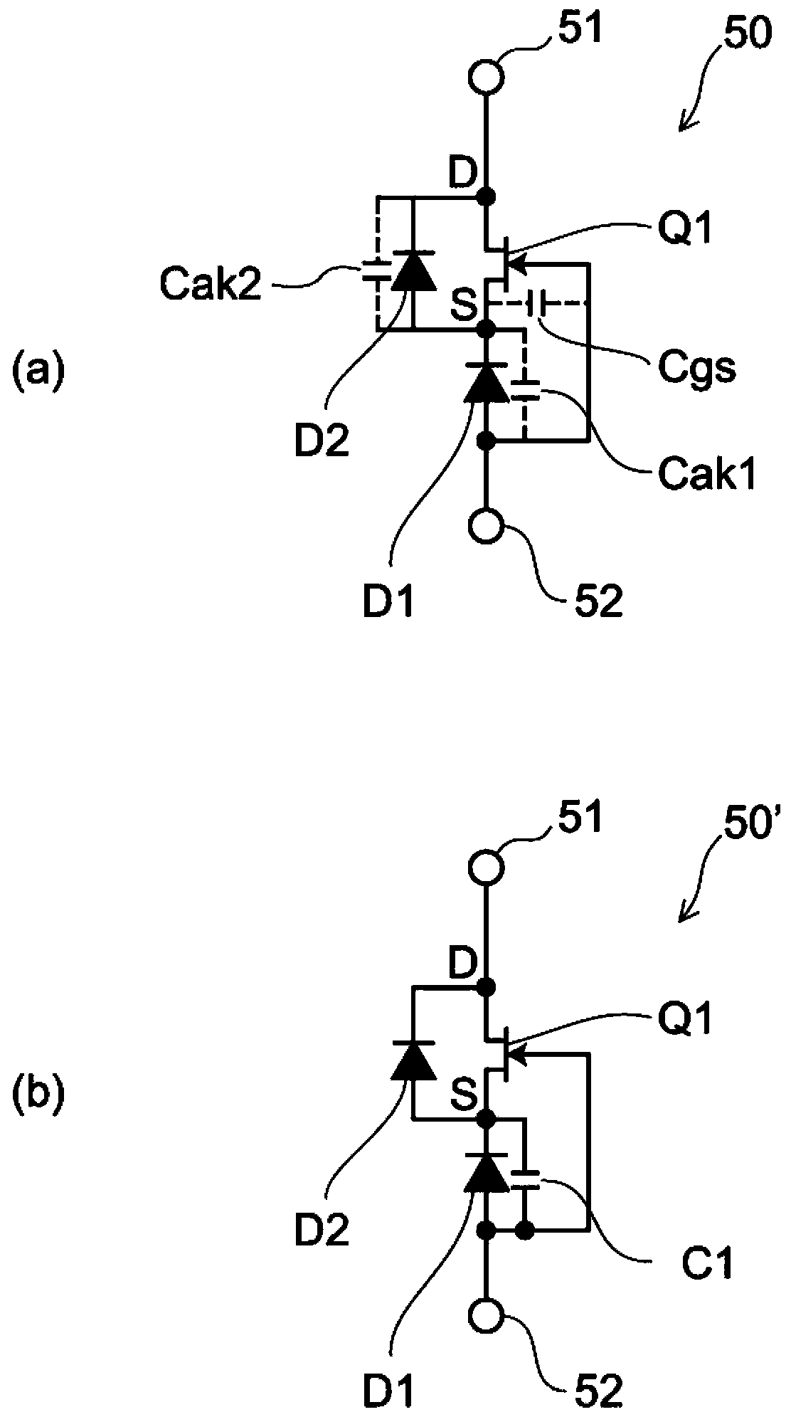
    Figure 3
Patent Text Reader

Abstract

According to an embodiment, a rectifier circuit includes a first diode, a switching element, and a second diode. The first diode is connected between a first terminal and a second terminal so that a direction toward the first terminal from the second terminal is in a forward direction. The switching element has a first main electrode connected to the first terminal, a second main electrode connected to a cathode of the first diode, and a gate electrode connected to an anode of the first diode. The second diode is connected in parallel with respect to the switching element so that a direction toward the first terminal from the cathode of the first diode is in a forward direction, between the first main electrode and the second main electrode of the switching element.
Need to check novelty before this filing date? Find Prior Art

Description

technical field

[0001] The invention relates to a rectifying circuit. Background technique

[0002] Conventionally, there has been proposed a rectifier circuit in which a unipolar FET (Field Effect Transistor: Field Effect Transistor) as a normally-on element and a diode are connected gate-cathode. The switching speed of this rectifier circuit depends on the diode, and the withstand voltage capability of the element depends on the FET.

[0003] When such a rectifier circuit is used, for example, as a freewheel diode of a switching power supply operating at high speed, the conduction may be delayed due to parasitic capacitance between the gate and the source of the FET.

[0004]

<a class='classify-link' href='https://eureka.patsnap.com/topic-patents-patent-literature'>Patent Literature</a>

[0005] [Patent Document 1] Japanese Patent Laid-Open No. 2008-198735 Contents of the invention

[0006] According to the embodiment, a rectifier circuit capable of high-speed operation is provided.

[0007] According to an embodiment, the rectifier circuit includes a first ...

Examples

Embodiment Construction

[0019] Embodiments will be described below with reference to the drawings. In addition, in each figure, the same code|symbol is attached|subjected to the same element.

[0020] figure 1 (a) is a circuit diagram of the rectifier circuit 50 of the embodiment.

[0021] The rectifier circuit 50 of the embodiment includes a switching element Q1 and a first diode D1 connected between a first terminal 51 and a second terminal 52 . The switching element Q1 and the first diode D1 are connected between the first terminal 51 and the second terminal 52 through a gate-cathode connection.

[0022] The first terminal 51 functions as a negative terminal of the rectifier circuit 50 , and the second terminal 52 functions as a positive terminal of the rectifier circuit 50 .

[0023] The switching element Q1 is a unipolar FET (Field Effect Transistor), and has a drain electrode as a first main electrode, a source electrode and a gate electrode as a second main electrode.

[0024] The switchin...