Large-rotation high-speed punching progressive die of multi-column electric motor stator

A motor stator, high-speed technology, applied in the field of multi-row motor stator large-turn high-speed punching and grading molds, can solve the problems of poor parallelism of iron cores, uneven thickness of raw materials, large differences, etc., to improve product quality and efficiency. Effect

Active Publication Date: 2014-08-27
宁波建欣精密模具有限公司
View PDF7 Cites 10 Cited by
  • Summary
  • Abstract
  • Description
  • Claims
  • Application Information

AI Technical Summary

Problems solved by technology

[0003] There is an existing motor inner stator iron core, which is formed by stacking multiple punched sheets. Due to the uneven thickness of the punched raw materials, for example, the same batch of iron sheets, one side is thicker and the other side is thinner. Such iron sheet raw materials are stamped If the obtained punching sheets are superimposed at the same angle, the obtained iron core will be thin on one side and the other side, with a large difference
Especially for high-end motors, the stator core has high requirements on coaxiality and parallelism. To meet the requirements, it is necessary to rotate each stator punching piece by 180 degrees to solve the problem, because the stator blanking concave of the existing high-speed punching die The molds are fixed and will not move, and the parallelism of the iron core will be out of tolerance due to the uneven thickness of the raw material for each stamping sheet; therefore, the existing high-speed progressive dies cannot meet the required requirements

Method used


Image

  • Large-rotation high-speed punching progressive die of multi-column electric motor stator
  • Large-rotation high-speed punching progressive die of multi-column electric motor stator

Examples


Embodiment Construction

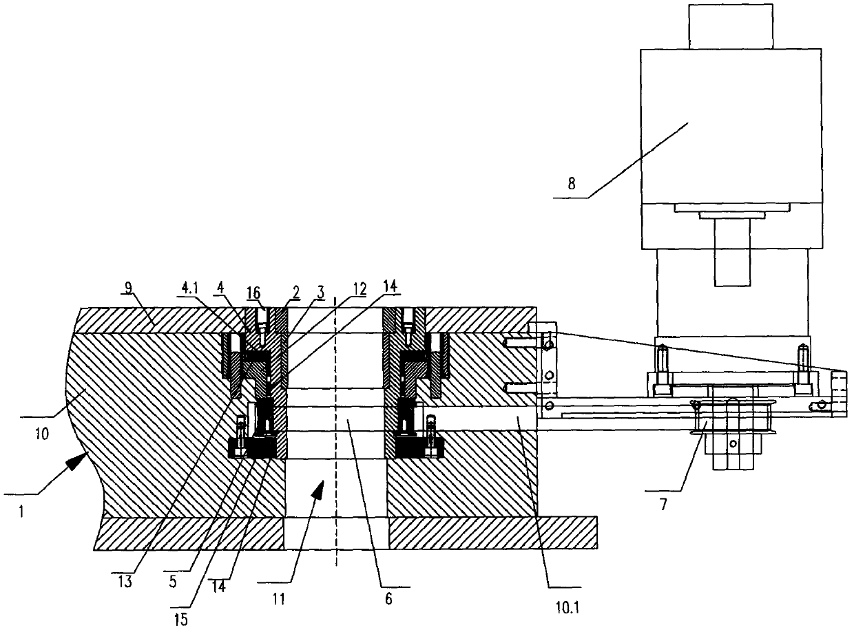
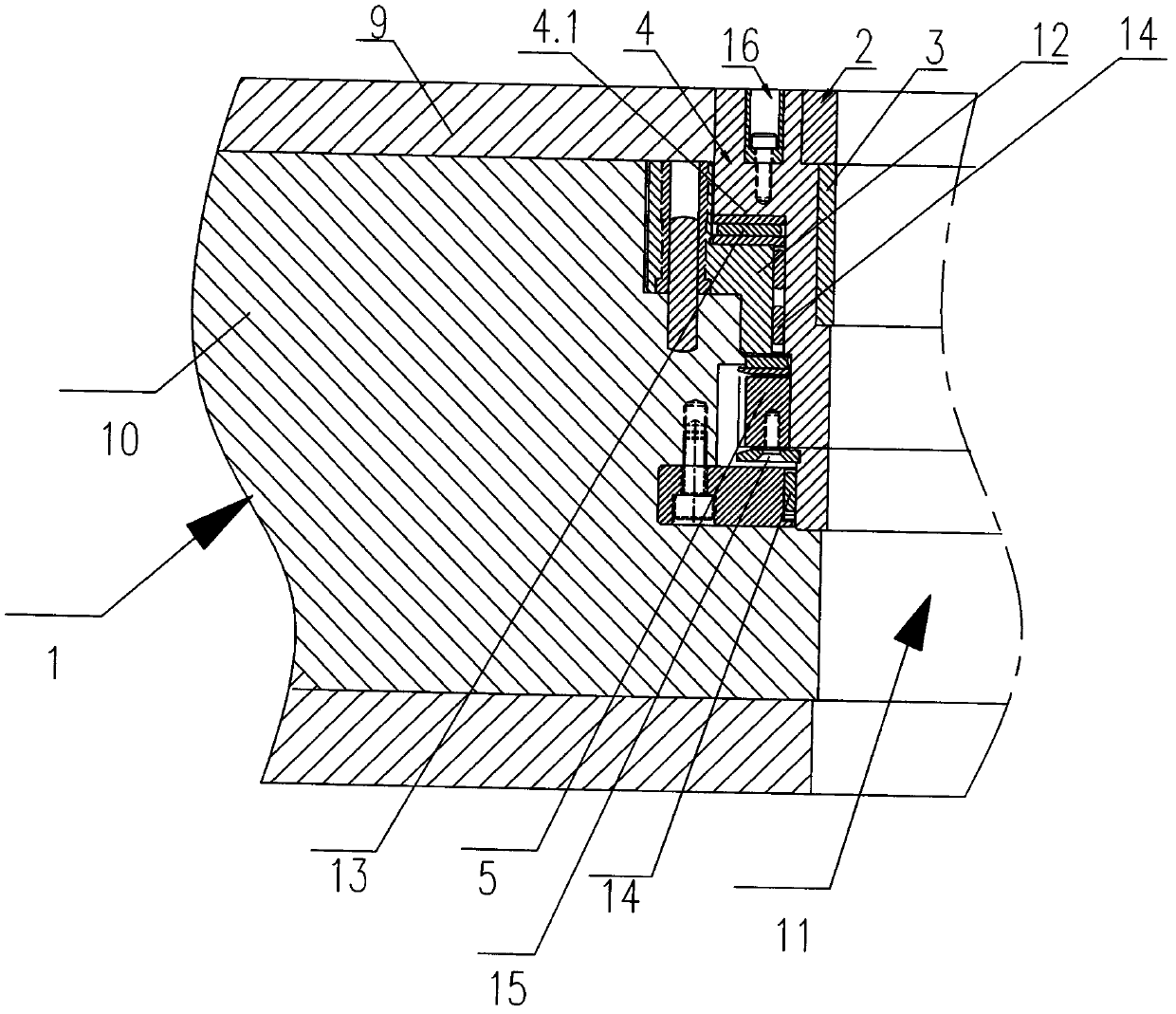
[0030] refer to figure 1 and figure 2 As shown, a multi-row motor stator large-rotation high-speed punching progressive die includes an upper die, a lower die 1, and other common features of existing progressive dies, such as multi-step stamping components, so it will not be described in detail here. This embodiment mainly describes the innovations of the present invention, and the present invention also includes a blanking die 2, a locking ring 3, a twist sleeve 4, a first synchronous wheel 5, a synchronous belt 6, a second synchronous wheel 7 and a servo motor 8, The lower mold 1 includes the concave template 9 and the lower mold base 10 from top to bottom. To limit and rotate in the circumferential direction; the blanking die 2 and the locking ring 3 are tightly fitted in the upper port of the twist sleeve 4, the locking ring 3 is located below the blanking die 2, and the inner diameter of the locking ring 3 is smaller than the blanking die The inner diameter of the die ...


PUM


Abstract

The invention relates to a large-rotation high-speed punching progressive die of a multi-column electric motor stator. The large-rotation high-speed grading die comprises an upper die, a lower die, a blanking concave die, a locking ring and a torsion sleeve, wherein the lower die comprises a concave die plate and a lower die seat, the upper end of the torsion sleeve is arranged in the concave die plate, the lower end of the torsion sleeve extends downwards into the lower die seat, the torsion sleeve and the lower die seat are axially position-specified and are in circumferential running fit, both of the blanking concave die and the locking ring are tightly matched in an upper port of the torsion sleeve, the locking ring is arranged below the blanking concave die, and the blanking concave die, the locking ring, the torsion sleeve and the lower die plate form a vertical blanking channel. During working, the blanking concave die rotates for a certain after each stamping, a previous punching sheet and a next punching sheet are alternately overlapped in a thick-thin manner, thus, the problem of very poor parallelism degree of a stator core due to non-uniform thickness difference of raw materials is effectively solved, high requirement of stator core coaxiality can be completely satisfied when multiple shaft holes are punched by the same set of die, and product quality and efficiency are improved. The large-rotation high-speed grading die belongs to the technical field of die equipment.

Description

technical field [0001] The invention belongs to the technical field of mold equipment, and in particular relates to a multi-row motor stator large-rotation high-speed punching and stepping mold. Background technique [0002] Progressive die (also called continuous die) is composed of multiple stations, and each station is connected in sequence to complete different processing, and a series of different stamping processes are completed in one stroke of the punching machine. After a stroke is completed, the punch feeder moves the material forward according to a fixed step, so that multiple processes can be completed on a pair of molds, generally including punching, blanking, bending, trimming, and stretching. etc. [0003] There is an existing motor inner stator iron core, which is formed by stacking multiple punched sheets. Due to the uneven thickness of the punched raw materials, for example, the same batch of iron sheets, one side is thicker and the other side is thinner. ...

Claims


Application Information

Patent Timeline
Patent Type & Authority Applications(China)
IPC IPC(8): B21D28/14
Inventor 邬建兵
Owner 宁波建欣精密模具有限公司
Why Eureka
Try Eureka