
A positioning device for visual inspection equipment

A technology for visual inspection and positioning device, which is applied to workpiece clamping devices, manufacturing tools, etc., and can solve problems such as visible defects in cylinder blocks.

Active Publication Date: 2015-12-30
日照新睿招商发展有限公司
View PDF5 Cites 0 Cited by
  • Summary
  • Abstract
  • Description
  • Claims
  • Application Information

AI Technical Summary

Problems solved by technology

Due to reasons such as production equipment or operating technology level, the cylinder block in actual production often has visible defects

Method used


Image

  • A positioning device for visual inspection equipment
  • A positioning device for visual inspection equipment
  • A positioning device for visual inspection equipment

Examples


Embodiment Construction

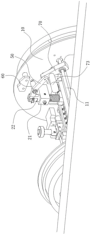
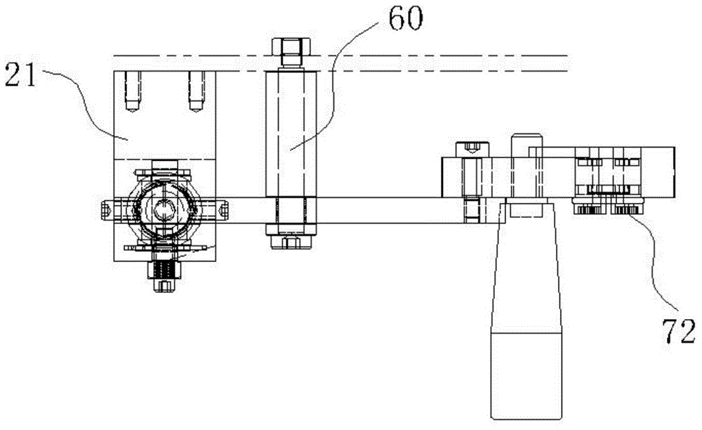
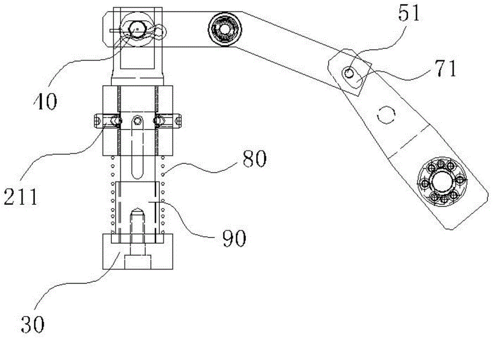
[0025] Such as Figure 1 to Figure 3 As shown, a positioning device for visual inspection equipment includes a shaft seat 21 fixed on the main body 10 of the visual inspection device, a first shaft 22 used in conjunction with the shaft seat 21, a positioning block 30 installed at one end of the first shaft 22, The first hinge pin 40 installed on the other end of the shaft 22 and the V-shaped block 50 connected with the first hinge pin 40 .

[0026] The shaft seat 21 is equipped with a ball plunger 211, a spring 80 and a metal collar 90 are arranged between the shaft seat 21 and the positioning block 30, and the second shaft 22 is connected between the ball plunger 211, the spring 80 and the metal shaft. Under the action of the ring 90, it can reciprocate in the axial direction.

[0027] A second hinge pin 60 is arranged in the middle of the V-shaped block 50 , and the second hinge pin 60 is fixed on the main body 10 of the visual inspection equipment, and the V-shaped block 5...


PUM


Abstract

The invention discloses a positioning device for appearance inspection equipment. The positioning device comprises a shaft base (21), a shaft (22), a positioning block (30) and a V-shaped block (50), wherein the positioning block (30) is installed at one end of the shaft (22), and the V-shaped block (50) is movably connected with the shaft (22). A hinge pin (60) is arranged in the middle of the V-shaped block (50). The V-shaped block (50) can rotate around the hinge pin (60). The positioning device further comprises a block (70) which is movably connected with the V-shaped block (50). The end, connected with the block (70), of the V-shaped block (50) is provided with a hinge pin (51). The end, connected with the V-shaped block (50), of the block (70) is provided with a groove (71). The hinge pin (51) can move in the groove (71). When the block (70) is rotated, as the action of the groove (71) in the block (70), the V-shaped block (50) drives the shaft (22) to descend, and the positioning block (30) at one end of the shaft (22) can be inserted into the sunken part of a cylinder body; in this way, the positioning effect on the cylinder body is achieved.

Description

technical field [0001] The invention relates to the field of appearance inspection equipment for parts, in particular to a positioning device for appearance inspection equipment. Background technique [0002] The cylinder of the automobile engine is an important actuator in the component. Due to reasons such as production equipment or operating technology level, there are often visible defects in the cylinder block in actual production. Therefore, it is necessary to carry out relevant appearance inspection before the cylinder block leaves the factory. The scope of appearance inspection mainly includes: all planes of the cylinder body should not have obvious protrusions, depressions, scratches and defects. Among them, the deformation depression formed due to the internal stress of the material is a common defect. [0003] The visual inspection equipment used to detect surface defects of the cylinder body should have the following functions: it can be shaken and rotated fre...

Claims


Application Information

Patent Timeline
Patent Type & Authority Patents(China)
IPC IPC(8): B25B11/00
CPCB25B11/00
Inventor 李国阳
Owner 日照新睿招商发展有限公司
Learn More