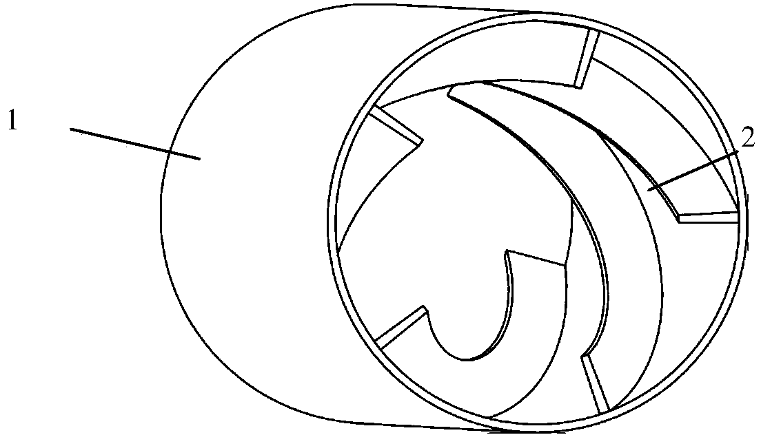
Flow guiding pipeline guiding fluid to spirally go forwards

A pipeline and fluid technology, applied in the direction of fluid flow, mechanical equipment, etc., can solve the problems of difficult to achieve ventilation effect, difficult to control the air flow, occupying space, etc., to achieve the effect of increasing the maximum air supply speed, occupying less space, and convenient manufacturing and installation

Active Publication Date: 2014-08-27
SOUTHEAST UNIV
View PDF5 Cites 6 Cited by
  • Summary
  • Abstract
  • Description
  • Claims
  • Application Information

AI Technical Summary

Problems solved by technology

However, these two kinds of fresh air systems have their own shortcomings in application: the one-way fresh air system has no special air supply duct, the air flow is not easy to control, and it is difficult to achieve a good ventilation effect; the fresh air of the two-way fresh air system passes through the fresh air host. and air supply pipes into the room, the pipes will take

Method used


Image

  • Flow guiding pipeline guiding fluid to spirally go forwards

Examples


Example Embodiment

[0017] Example one

[0018] Such as figure 1 Shown is a diversion pipe that guides the fluid to enter. The pipe body is injection molded from PVC material. The inner diameter of the pipe is 100mm and the length is 300mm. The thickness of the pipe wall and the thickness of the fin can be determined according to the actual situation. The spiral fins are injection molded together with the pipe. The height of the spiral fin is not less than 10% of the inner diameter of the tube. The number and length of the spiral fin can be determined according to the actual situation. The spiral fin is evenly arranged around the tube wall. The spiral angle of the spiral fin (the angle between the tangent of the spiral and the axis) is not greater than 25°, and the number of turns of a single spiral fin around the axis is within three cycles. The diversion duct is connected with the air outlet of the blower to optimize the air flow out of the blower.

Example Embodiment

[0019] Example two

[0020] The difference between this embodiment and the first embodiment is that the pipe is divided into two parts: a tube body and a fin. The pipe body is injection molded from PVC material. The inner diameter of the pipe is 100mm and the length is 300mm. The thickness of the pipe wall can be determined according to the actual situation. The inner wall of the pipe is preset with spiral grooves for connecting spiral fins. The grooves are the same It is injection molded together with the tube body. The fin material is a flexible metal sheet, and the spiral fin is formed by inserting the metal sheet into the groove during installation.


PUM

PropertyMeasurementUnit
Lengthaaaaaaaaaa
The inside diameter ofaaaaaaaaaa
Lengthaaaaaaaaaa

Abstract

A flow guiding pipeline guiding fluid to spirally go forwards is characterized in that the flow guiding pipeline is composed of a common pipeline and a plurality of spiral fins arranged on the inner surface of the common pipeline. A plurality of parallel spiral lines are arranged on the wall of the pipeline, and the spiral fins are arranged with the spiral lines as base lines. The spiral angle of each spiral line, namely the included angle between a tangent line of each spiral line and the axis of each spiral line is not larger than 25 degrees, the spiral circle number of each spiral line is not larger than three, and the thickness of each spiral fin is smaller than 8% of the inner diameter of the flow guiding pipeline. The height of each spiral fin is larger than or equal to 10% of the diameter of the flow guiding pipeline. The flow guiding pipeline is arranged on an air outlet of a fresh air blower, airflow passes through the flow guiding pipeline to spirally go forwards, and the air blowing depth is obviously increased. The flow guiding pipeline is simple in structure and convenient to manufacture and mount, most flow guiding pipelines of a dual-direction fresh air system can be omitted, and occupied indoor space of air supply ducts is reduced.

Description

technical field [0001] The invention relates to a diversion pipe, in particular to a diversion pipe in which several helical fins are arranged on the inner surface of the pipe to guide the fluid to precess and speed up before flowing out of the pipe. Background technique [0002] As we all know, environmental pollution is becoming more and more serious nowadays, and air pollution directly affects the lives of residents. On days when air pollution is serious, opening windows for ventilation is not beneficial to people's physical and mental health. Moreover, with the improvement of the living standards of domestic residents, air conditioners have been widely used in buildings. When the air conditioners are enabled, the windows are usually closed. The long-term closing of windows is not conducive to ventilation, and it is impossible to discharge organic volatiles such as formaldehyde and benzene released by interior decoration materials and furniture in a timely manner, as well...

Claims


Application Information

Patent Timeline
IPC IPC(8): F15D1/02
Inventor 傅秀章李祥宁董剑
Owner SOUTHEAST UNIV
Why Eureka
Try Eureka