A liquid crystal television with infrared positioning function and its infrared positioning method
What is AI technical title?
AI technical title is built by Patsnap AI team. It summarizes the technical point description of the patent document.
A positioning method and LCD TV technology, applied in the direction of electrical components, non-electrical signal transmission systems, signal transmission systems, etc., can solve problems such as development costs and complex structures, and achieve simple and easy technical principles, enhanced functional effects, and low cost Effect
Active Publication Date: 2017-03-08
SHENZHEN SKYWORTH RGB ELECTRONICS CO LTD
View PDF4 Cites 0 Cited by
Summary
Abstract
Description
Claims
Application Information
AI Technical Summary
This helps you quickly interpret patents by identifying the three key elements:
Problems solved by technology
Method used
Benefits of technology
Problems solved by technology
[0004] In view of the above-mentioned deficiencies in the prior art, the present invention provides an LCD TV with infrared positioning function and its infrared positioning method, aiming to solve the problems of development cost and complex structure of this technology
Method used
Image
Click on the blue label to locate the original text in one second.
Reading with bidirectional positioning of images and text.
Examples
Embodiment 1
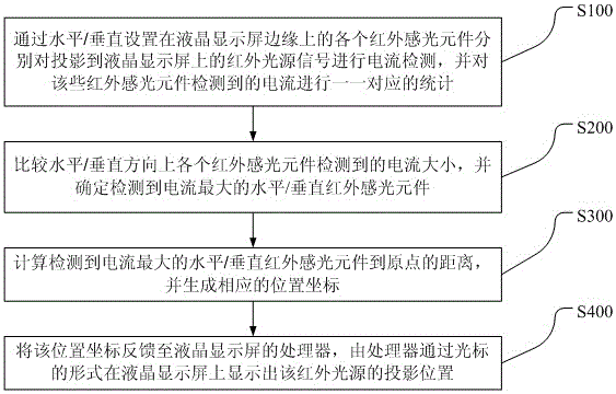
[0051] See figure 1 , figure 1 It is the implementation flowchart of Embodiment 1 of the infrared positioning method for liquid crystal display screens of the present invention.
[0052] Such as figure 1 Shown, described infrared positioning method for liquid crystal display, it comprises steps:
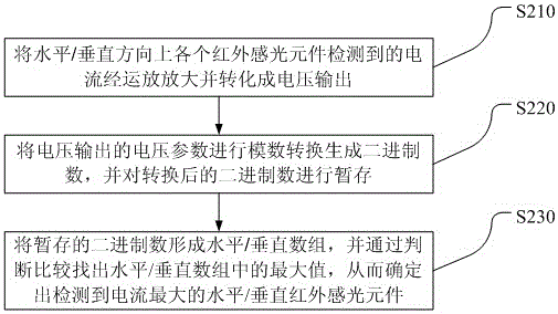
[0053] Step S100, through the infrared photosensitive elements arranged horizontally / vertically on the edge of the liquid crystal display screen, respectively detect the current of the infrared light source signal projected on the liquid crystal display screen, and make a one-to-one correspondence between the currents detected by these infrared photosensitive elements registration.
[0054] Wherein, the current data collected in the horizontal direction and the vertical direction are independent of each other, and correspondingly, the horizontal direction and the vertical direction are also completely separated when the current magnitude is compared subsequently.
[0055] In this...
Embodiment 2
[0082] See Figure 4 , Figure 4 It is a logic flow chart of Embodiment 2 of the infrared positioning method used for liquid crystal display screens of the present invention, and the present invention is further explained in conjunction with specific embodiments:
[0083] Such as Figure 4 As shown, the method embodiment includes:
[0084] In step a, the TV is turned on and in the state of waiting to receive a position signal, and then enters step b;
[0085] Step b, there is an infrared light source in front of the TV, and then enter step c or step f;
[0086] Step c, when the infrared light source is directly in front of the TV screen, then enter step d;
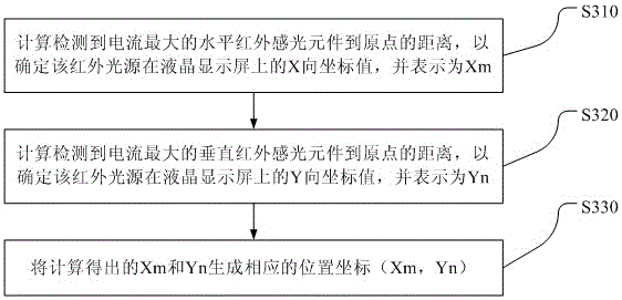
[0087] In step d, distance coordinates (Xm, Yn) are given for both horizontal and vertical photosensitive reception, and then enter step e;
[0088] Step e, the TV chip receives the position signal and processes and displays the corresponding action on the screen, which is completed;
[0089] Generate another branch ...
PUM
Abstract
The invention discloses a liquid crystal display television with an infrared positioning function and an infrared positioning method of the liquid crystal display television. The method includes the steps that all infrared light sensing elements horizontally / perpendicularly arranged on the edge of a liquid crystal display screen are used for conducting current detection on infrared light source signals respectively, wherein the infrared light source signals are projected on the liquid crystal display screen, and one-to-one corresponding statistics is conducted on currents detected by the infrared light sensing elements; the currents detected by the infrared light sensing elements in the horizontal / perpendicular direction are compared, and the horizontal / perpendicular infrared light sensing element detecting the largest currents is determined; the distance between the horizontal / perpendicular infrared light sensing element detecting the largest currents and a point of origin is calculated, and corresponding position coordinates are generated; the position coordinates are fed back to a processor of the liquid crystal display screen, and the projection position of an infrared light source is displayed on the liquid crystal display screen through the processor in a cursor mode; the liquid crystal display television can have the infrared positioning function, and the functional effect of interactive entertainment between a user and the television is enhanced.
Description
technical field [0001] The invention relates to the field of liquid crystal display manufacturing, in particular to a liquid crystal television with an infrared positioning function and an infrared positioning method thereof. Background technique [0002] At present, there are many positioning technologies on the market that are a certain distance away from the LCD screen, that is, the user can control the content on the LCD screen within a certain distance from the LCD screen, which is similar to the game operation of cutting fruit in the air, but this Not only the cost of new technology products cannot be controlled, but also the structure is relatively complex, and the corresponding effect is not satisfactory. It can be said that in the field of liquid crystal screen sensing, this technology is still close to the initial development stage, and there is still room for further development. [0003] Therefore, the prior art still needs to be improved and developed. Conten...
Claims
Application Information
Patent Timeline
Application Date:The date an application was filed.
Publication Date:The date a patent or application was officially published.
First Publication Date:The earliest publication date of a patent with the same application number.
Issue Date:Publication date of the patent grant document.
PCT Entry Date:The Entry date of PCT National Phase.
Estimated Expiry Date:The statutory expiry date of a patent right according to the Patent Law, and it is the longest term of protection that the patent right can achieve without the termination of the patent right due to other reasons(Term extension factor has been taken into account ).
Invalid Date:Actual expiry date is based on effective date or publication date of legal transaction data of invalid patent.

