
X-ray tube to power supply connector

A technology of electrical connectors and power supplies, which can be used in X-ray tube components, X-ray equipment, connections, etc., and can solve problems such as air inclusions

Inactive Publication Date: 2014-08-27
MOXTEK INC
View PDF6 Cites 7 Cited by
  • Summary
  • Abstract
  • Description
  • Claims
  • Application Information

AI Technical Summary

Problems solved by technology

Another possible difficulty with this design could be entrapped air

Method used


Image

  • X-ray tube to power supply connector
  • X-ray tube to power supply connector
  • X-ray tube to power supply connector

Examples


Embodiment Construction

[0035] definition

[0036] As used herein, the term "annular" includes non-circular annulus. Thus, for example, the shape of the annular surface of the plug (which may surround the plug at its base) is not limited to circular inner and outer peripheries. The general shape of the annular surface of the plug will be a circular inner perimeter to allow twisting of the plug in the receptacle and a square outer perimeter to match the shape of the outer metal housing or shield.

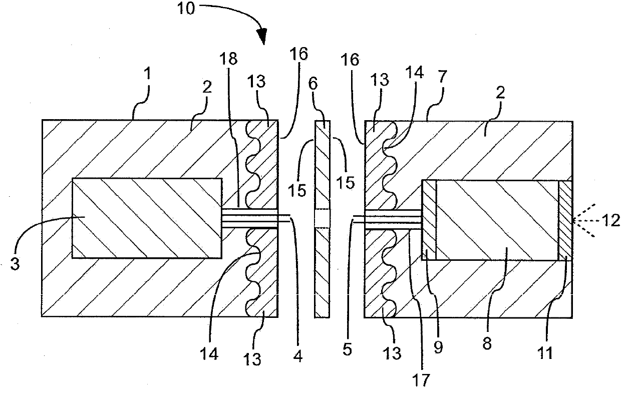
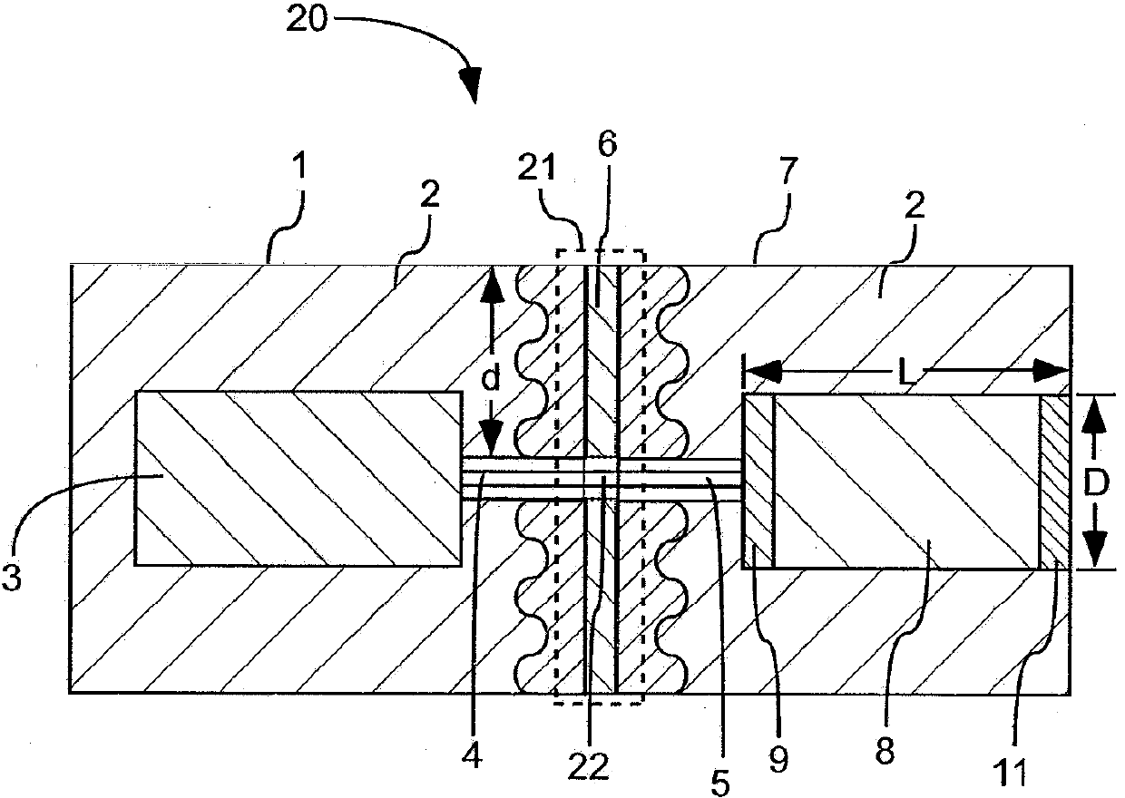
[0037] figure 1 with 2 X-ray sources 10 and 20 are shown. The power supply 3, x-ray tube 8 and spacer 6 are shown as figure 1 separate components in the x-ray source, but in figure 2 The x-ray source 20 is shown coupled together, thereby illustrating how the power source 3 and x-ray tube 8 can be repeatedly coupled and separated without damaging the power source 3 or x-ray tube 8 .

[0038] The housing 1 can accommodate a power source 3 . The power source 3 can be embedded in the electrically insulati...


PUM


Abstract

An x-ray source can include an x-ray tube and a power supply. The x-ray tube can be removably affixed to the power supply in a rigid manner with the x-ray tube movable and holdable along with the power supply when affixed thereto. A releasable coupling between the x-ray tube and the power supply can create an interface defining a potential arc path. A means, such as a non-linear plug and socket junction, a gasket, or an electrically conductive sleeve, can be used for resisting arcing along the potential arc path.

Description

[0001] priority statement [0002] Priority is claimed to U.S. Provisional Patent Application Serial No. 61 / 579,158, filed December 22, 2011, and U.S. Nonprovisional Patent Application Serial No. 13 / 493,695, filed June 11, 2012, which are hereby incorporated by reference in their entirety way incorporated into this article. technical field [0003] The present invention generally relates to x-ray tubes and x-ray tube power supplies. Background technique [0004] Common x-ray tube and power supply configurations are both intended to be integrally combined and have a continuous, electrically insulating encapsulation material surrounding the two devices. The entire unit may be surrounded by an enclosure, typically at ground voltage. The electrical insulating material insulates the x-ray tube and high voltage components of the power supply from the enclosure. [0005] The reason for integrally combining the two devices in this way is that there can be tens of kilovolts of vol...

Claims


Application Information

Patent Timeline
Patent Type & Authority Applications(China)
IPC IPC(8): H05G1/10H01J35/02
CPCH01R13/53H01R2103/00H05G1/10H01R13/2421H01R13/533
Inventor W·H·汉森B·L·泰勒D·雷纳德D·王
Owner MOXTEK INC
Learn More