
Speed reducer and assembly type mechanical sealing structure thereof

A technology of mechanical seals and reducers, applied in mechanical equipment, transmission parts, belts/chains/gears, etc., can solve the problems of unrealistic and incapable installation of oil seals

Inactive Publication Date: 2014-09-10
JIANGSU HEFUTE GEAR MFG
View PDF7 Cites 0 Cited by
  • Summary
  • Abstract
  • Description
  • Claims
  • Application Information

AI Technical Summary

Problems solved by technology

[0002] In the field of reducer technology, for some output parts with limited installation space, if a conventional labyrinth mechanical seal is used, it will cause the situation that it cannot be installed, and it is even more unrealistic to use an oil seal. A sealing structure that meets the requirements of space installation and can achieve the effect of mechanical sealing

Method used


Image

  • Speed reducer and assembly type mechanical sealing structure thereof
  • Speed reducer and assembly type mechanical sealing structure thereof

Examples


Embodiment Construction

[0018] The present invention will be further described now in conjunction with accompanying drawing. These drawings are simplified schematic diagrams only to illustrate the basic structure of the present invention in a schematic way, so they only show the components relevant to the present invention.

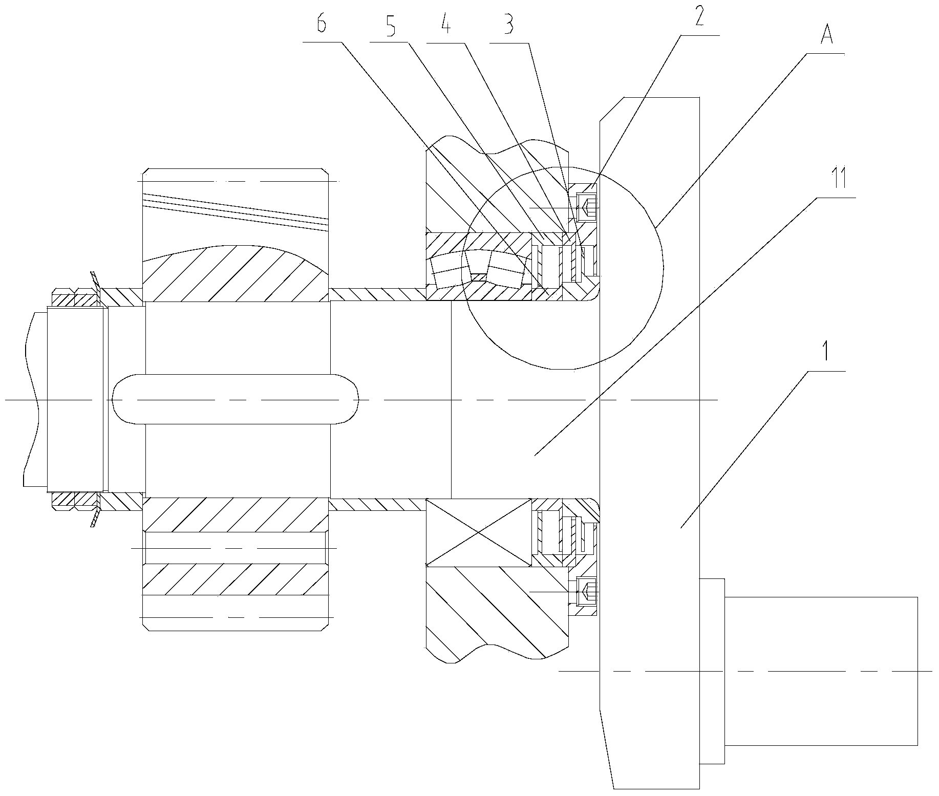
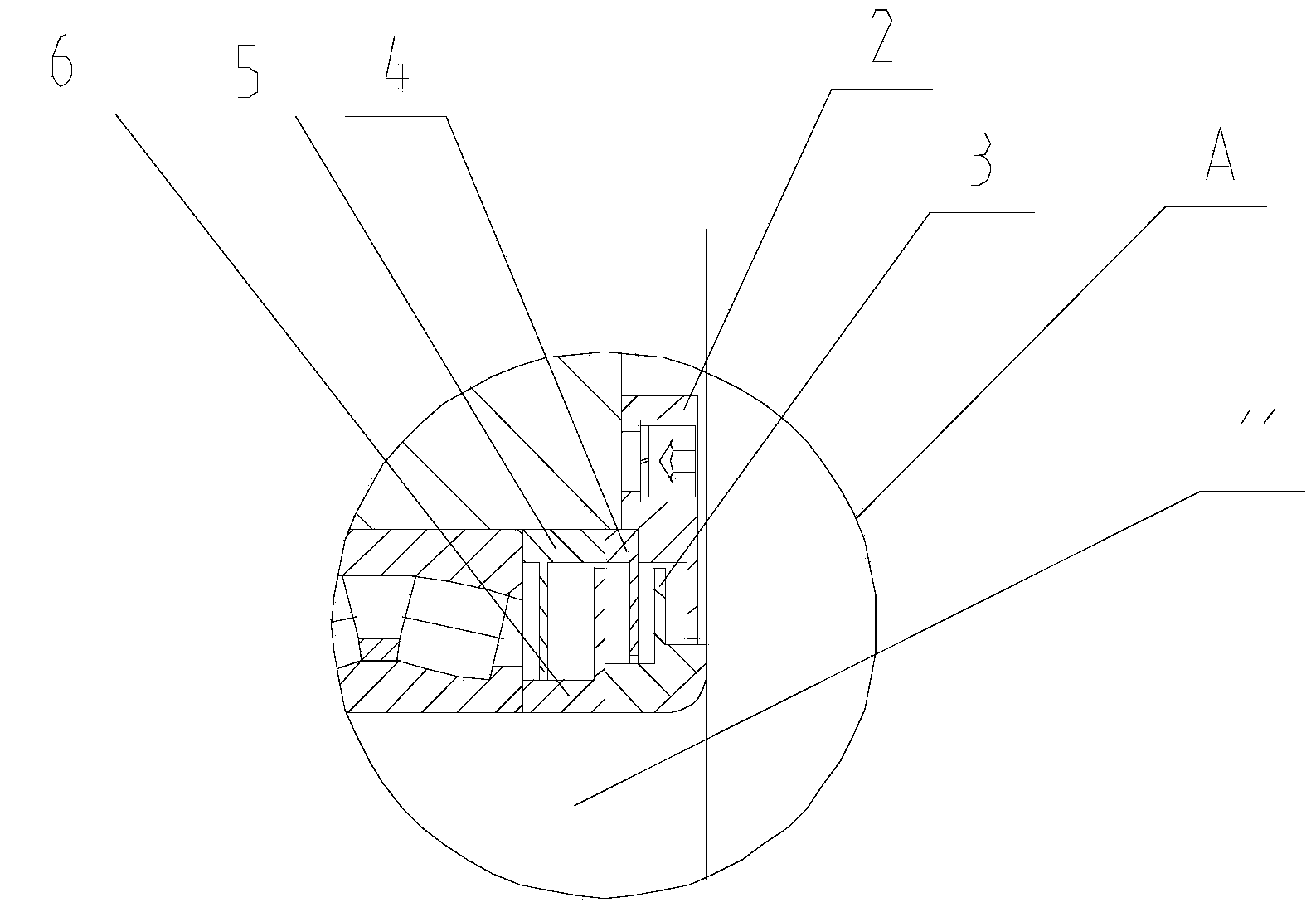
[0019] Such as figure 1 As shown, an assembled mechanical seal structure of a reducer has a crankshaft 1, and the crankshaft 1 has a rotating shaft 11, and the rotating shaft 11 is installed into the transparent cover 2 from the left side, and the transparent cover 2 is located at the rightmost end of the rotating shaft 11, and the transparent cover 2 has The first vertical barrier, the first inner partition ring 3 is installed on the left side of the transparent cover 2, the first inner partition ring 3 has a second vertical barrier, the first vertical barrier of the transparent cover 2 and the first inner partition ring The extension direction of the second vertical partition...


PUM


Abstract

The invention relates to a speed reducer and an assembly type mechanical sealing structure thereof. The assembly type mechanical sealing structure of the speed reducer is provided with a crankshaft, the crankshaft is provided with a rotary shaft, the rightmost end of the rotary shaft is mounted into a penetration cover, a first inner partition ring is mounted on the left side of the penetration cover, and a first vertical baffle of the penetration cover and a second vertical baffle of the first inner partition form a first labyrinth seal layer. A second inner partition ring is mounted on the left side of a first outer partition ring, a second outer partition ring is mounted on the left side of a second inner partition ring, a fourth vertical baffle of the second inner partition ring and a fifth vertical baffle of the second outer partition ring form a second labyrinth seal layer.

Description

technical field [0001] The invention relates to the technical field of reducers, in particular to a reducer assembled mechanical seal structure and a reducer. Background technique [0002] In the field of reducer technology, for some output parts with limited installation space, if a conventional labyrinth mechanical seal is used, it will cause the situation that it cannot be installed, and it is even more unrealistic to use an oil seal. It is a sealing structure that meets the space installation requirements and can achieve the effect of mechanical sealing. Contents of the invention [0003] The technical problem to be solved by the present invention is to overcome the deficiencies of the prior art, and provide an assembled mechanical seal structure of the reducer and the reducer which can save installation space and can be effectively sealed. [0004] The technical solution adopted by the present invention to solve the technical problem is: a reducer assembly type mecha...

Claims


Application Information

Patent Timeline
IPC IPC(8): F16H57/029
CPCF16H57/029
Inventor 王福龙钱江
Owner JIANGSU HEFUTE GEAR MFG
Features
  • Generate Ideas
  • Intellectual Property
  • Life Sciences
  • Materials
  • Tech Scout
  • Unparalleled Data Quality
  • Higher Quality Content
  • 60% Fewer Hallucinations
Learn More