BN ion door and manufacturing method thereof

A manufacturing method and ion gate technology, which are applied in the field of analytical instruments and can solve problems such as instability and uneven radial electric field of BN ion gates.

Active Publication Date: 2014-09-17
SHENZHEN GRADUATE SCHOOL TSINGHUA UNIV
View PDF3 Cites 13 Cited by
  • Summary
  • Abstract
  • Description
  • Claims
  • Application Information

AI Technical Summary

Problems solved by technology

[0006] The main purpose of the present invention is to provide a BN ion gate and its manufacturing method, so a

Method used


Image

  • BN ion door and manufacturing method thereof
  • BN ion door and manufacturing method thereof
  • BN ion door and manufacturing method thereof

Examples


Embodiment 1

[0085] The present embodiment provides a method for manufacturing a BN ion gate, the method comprising the following steps:

[0086] S1, providing an insulating substrate and metal wires;

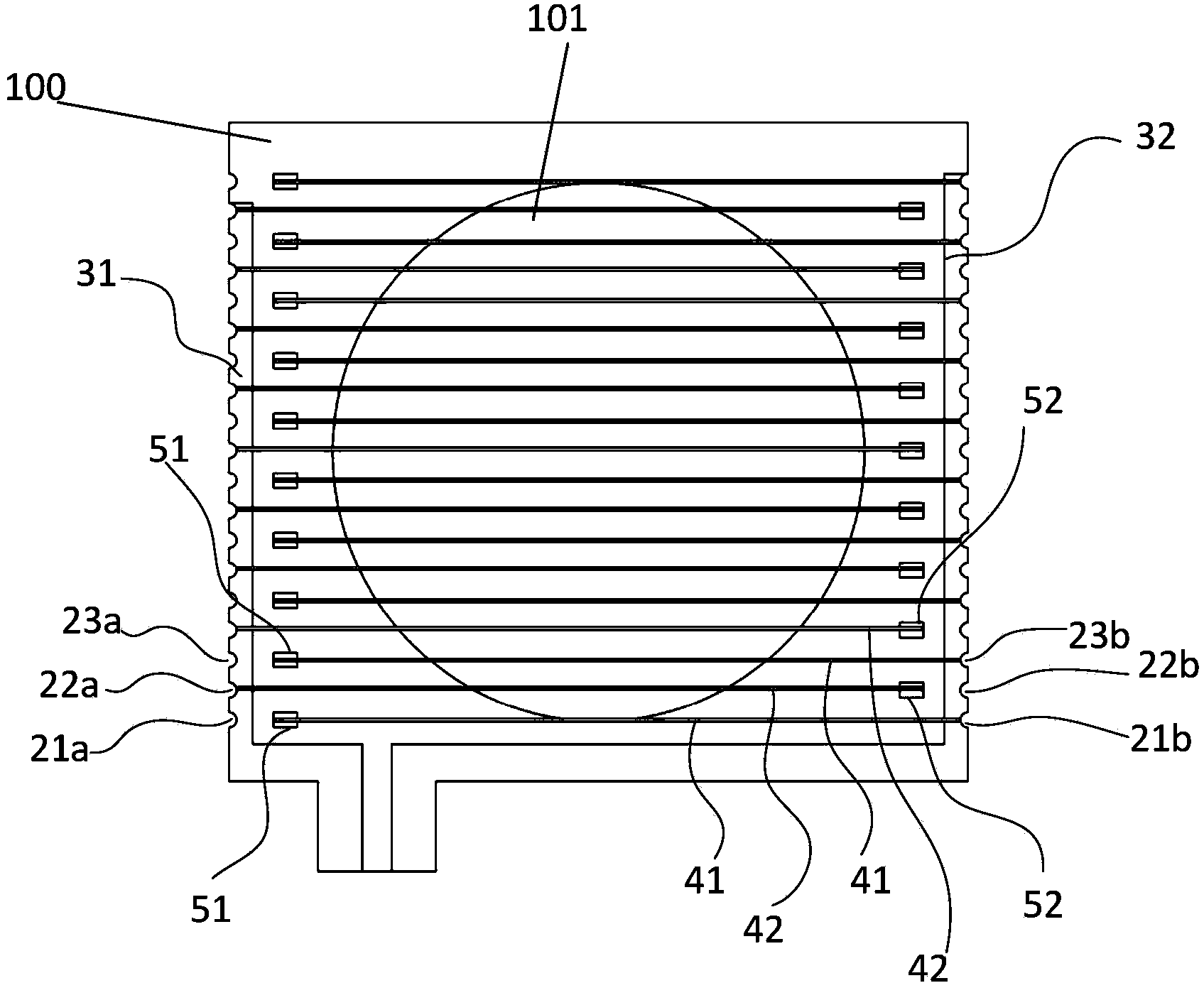
[0087]S2. Provide a gradual preload to act on the metal wire, so that the metal wire is wound on the insulating substrate, so as to form a plurality of parallel and equidistantly arranged metal wires on the same surface of the insulating substrate segment, and a plurality of the wire segments form a first wire group and a second wire group that are alternately arranged and insulated from each other, and each of the wire segments has the same internal tension; wherein each of the metal The wire segments require different pre-tightening forces, and the pre-tightening forces gradually decrease from the first wire segment to the last wire segment, so that the i-th wire segment to be wound is subject to its corresponding pre-tightening force. The stretched length of the insulating substrate is ...

Embodiment 2

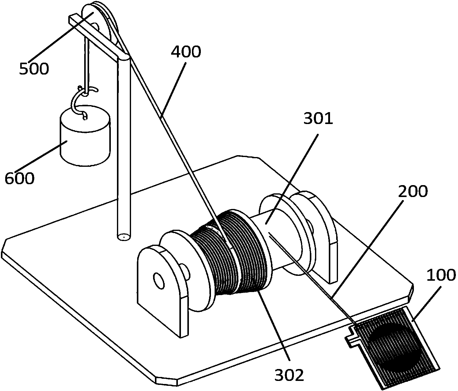
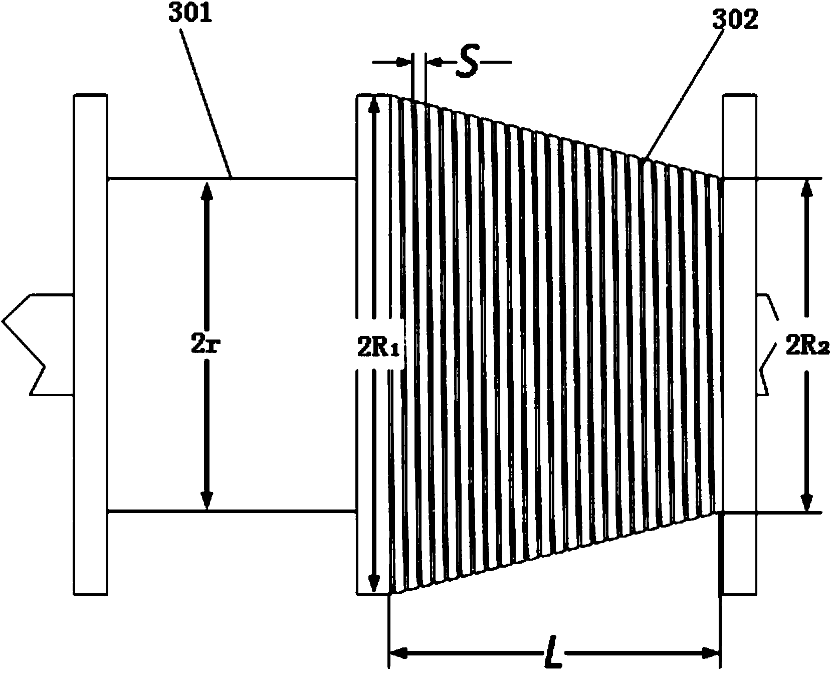
[0122] The difference between the manufacturing method of the BN ion gate provided in this embodiment and that of Embodiment 1 is that the tension conversion mechanism that provides the pre-tightening force provides a gradual pre-tightening force by continuously changing the quality of the weights, so the tension conversion in this embodiment Exist following difference in mechanism and embodiment 1: as Figure 5 As shown, the tension conversion shaft includes a first cylinder 301a and a second cylinder 302a for winding the metal wire 200, and the tension wire of the weight is fixed on the second cylinder 302a and can be wound on the cylindrical surface thereof. In a preferred solution, there is a protruding circular partition plate between the cylinder surface of the first cylinder 301a and the cylinder surface of the second cylinder 302a.

[0123] Based on the above differences, in this embodiment, the parameters of the first cylinder and the second cylinder of the tension co...


PUM


Abstract

The invention discloses a BN ion door and a manufacturing method thereof. The method includes the steps that (S1) an insulation substrate and a metal wire are provided, (S2) pretightening force which becomes smaller gradually is applied on the metal wire so that the metal wire can be wound onto the insulation substrate and multiple metal wire sections which are parallel with one another and distributed at an equal interval are formed on the same face of the insulation substrate, and the metal wire sections form a first metal wire set and a second metal wire set which are distributed alternately and are mutually insulated, wherein all the metal sections have identical internal tensioning force, gradually changing pretightening force is applied so that the length of the to-be-wound ith metal wire section which extends after bearing the corresponding tightening force is equal to that of the insulation substrate pressed by the wound i-1th metal wire section, the to-be-wound metal wire section which extends after bearing the tensioning force is as long as the insulation substrate pressed by the wound metal wire section, and i is a positive integer. Radial electric fields, manufactured in the method, of the BN ion door are uniform and stable.

Description

technical field [0001] The invention relates to the field of analytical instruments, in particular to a BN ion gate and a manufacturing method thereof. Background technique [0002] An ion gate is a device that controls the movement of ions in analytical instruments such as ion mobility spectrometry, time-of-flight mass spectrometry, and electron microscopy. By applying a potential difference between two sets of metal wires that are alternately arranged in parallel, a deflection electric field or a blocking electric field perpendicular to the original movement direction of ions is formed, which can deflect the trajectory of ions or block the movement of ions. [0003] There are many types of ion gates for controlling ion movement in the prior art, among which the Bradbury-Nielsen (BN) ion gate is the most widely used. The BN ion gate is composed of two groups of parallel metal wires that are insulated from each other and arranged alternately at equal intervals on the same p...

Claims


Application Information

Patent Timeline
IPC IPC(8): H01J9/00H01J3/26
Inventor 倪凯郭静然欧光礼张小郭余泉钱翔王晓浩
Owner SHENZHEN GRADUATE SCHOOL TSINGHUA UNIV
Why Eureka
Try Eureka