
Rotor for television frame with improved structure

A technology for TV rack and structure improvement, applied in the direction of machine/stand, supporting machine, mechanical equipment, etc., can solve problems such as inconvenience of use, automatic downward sliding, increase in depression angle, etc., and achieve the effect of avoiding repeated adjustment

Active Publication Date: 2014-09-24
KUNSHAN HONGJIE ELECTRONICS CO LTD
View PDF6 Cites 9 Cited by
  • Summary
  • Abstract
  • Description
  • Claims
  • Application Information

AI Technical Summary

Problems solved by technology

[0002] At present, the front and rear (pitch) angle adjustment of the TV stand is realized through the cooperation of round holes and arc-shaped holes. After the TV is adjusted to a suitable angle, under its own gravity, it will automatically go down when used for a long time Sliding, causing the depression angle to increase, requiring readjustment, causing inconvenience to use

Method used


Image

  • Rotor for television frame with improved structure
  • Rotor for television frame with improved structure

Examples


Embodiment

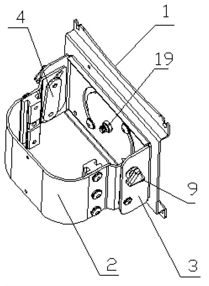
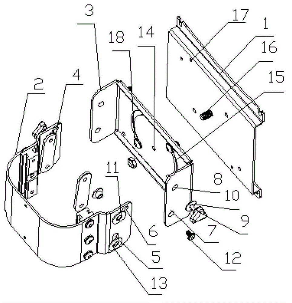
[0013] Embodiment: A structure-improved rotator for a TV stand, including a hanging plate 1, first and second connecting plates 2, 3, first and second connecting pieces and a pair of elongated connecting pieces 4, the first The first and second connecting plates 2 and 3 are both in a U-shaped structure, the second connecting plate 3 is sleeved on the outside of the first connecting plate 2, and the first and second connecting holes 5 are correspondingly provided on the two opposite side walls of the first connecting plate 2 , 6, the first connection hole 5 is a strip-shaped straight hole (vertical hole or horizontal hole) extending along the length direction of the first connection plate 2 or along the length direction perpendicular to the first connection plate 2, and the second connection hole 6 It is an elongated inclined hole forming an angle with the first connecting hole 5, and the first and second round holes 7 corresponding to the positions of the first and second conne...


PUM


Abstract

The invention discloses a rotor for a television frame with an improved structure. Both a first connecting plate and a second connecting plate are U-shaped; the second connecting plate sleeves the outer side of the first connecting plate; a first connecting hole and a second connecting hole are formed in the side wall of the first connecting plate; the first connecting hole is a vertical or horizontal elongated straight hole; the second connecting hole is an elongated inclined hole; a first circular hole and a second circular hole corresponding to the positions of the first connecting hole and the second connecting hole are formed in the two opposite side walls of the second connecting plate; a first connecting piece penetrates in the first connecting hole and the first circular hole and is finally connected with one end of a connecting sheet in a fastening way; a second connecting piece penetrates in the second circulating hole and the second circular hole and is finally connected the other end of the connecting sheet in the fastening way; the second connecting piece can be kept at any position in the second connecting hole; the hanging plate is connected with one side, back to the first connecting plate, of the second connecting plate; a mounting structure for mounting a television is arranged on the hanging plate. According to the rotor for the television frame with the improved structure, a pitch angle of the television in a long-term using process can be kept unchanged all the time, and repeated adjustment is avoided.

Description

technical field [0001] The invention relates to a connecting device for a TV frame, in particular to a structure-improved rotating head for a TV frame. Background technique [0002] At present, the front and rear (pitch) angle adjustment of the TV stand is realized through the cooperation of round holes and arc-shaped holes. After the TV is adjusted to a suitable angle, under its own gravity, it will automatically go down when used for a long time. Sliding will cause the depression angle to increase and need to be readjusted, causing inconvenience to use. Contents of the invention [0003] In order to overcome the above-mentioned defects, the present invention provides a rotator for a TV stand with an improved structure, and the rotator for a TV stand with an improved structure can keep the TV pitch angle stable. [0004] The technical solution adopted by the present invention in order to solve the technical problems: a structurally improved rotary head for TV racks, incl...

Claims


Application Information

Patent Timeline
Patent Type & Authority Applications(China)
IPC IPC(8): F16M11/06F16M11/16
Inventor 常晓杰
Owner KUNSHAN HONGJIE ELECTRONICS CO LTD
Learn More