

Electronic equipment and control method thereof
A technology of electronic equipment and auxiliary body, applied in the field of electronics, can solve the problems of cumbersome process, low operation efficiency, inconvenient state switching, etc.
- Summary
- Abstract
- Description
- Claims
- Application Information
AI Technical Summary
Problems solved by technology
Method used
Image

Examples
Embodiment Construction
[0052] The invention provides an electronic device and a control method, which are used to solve the problems in the prior art that state switching is inconvenient, the process is cumbersome, and the operation efficiency is low.
[0053] The technical solution in the embodiments of the present invention is to solve the above-mentioned technical problems, and the general idea is as follows:
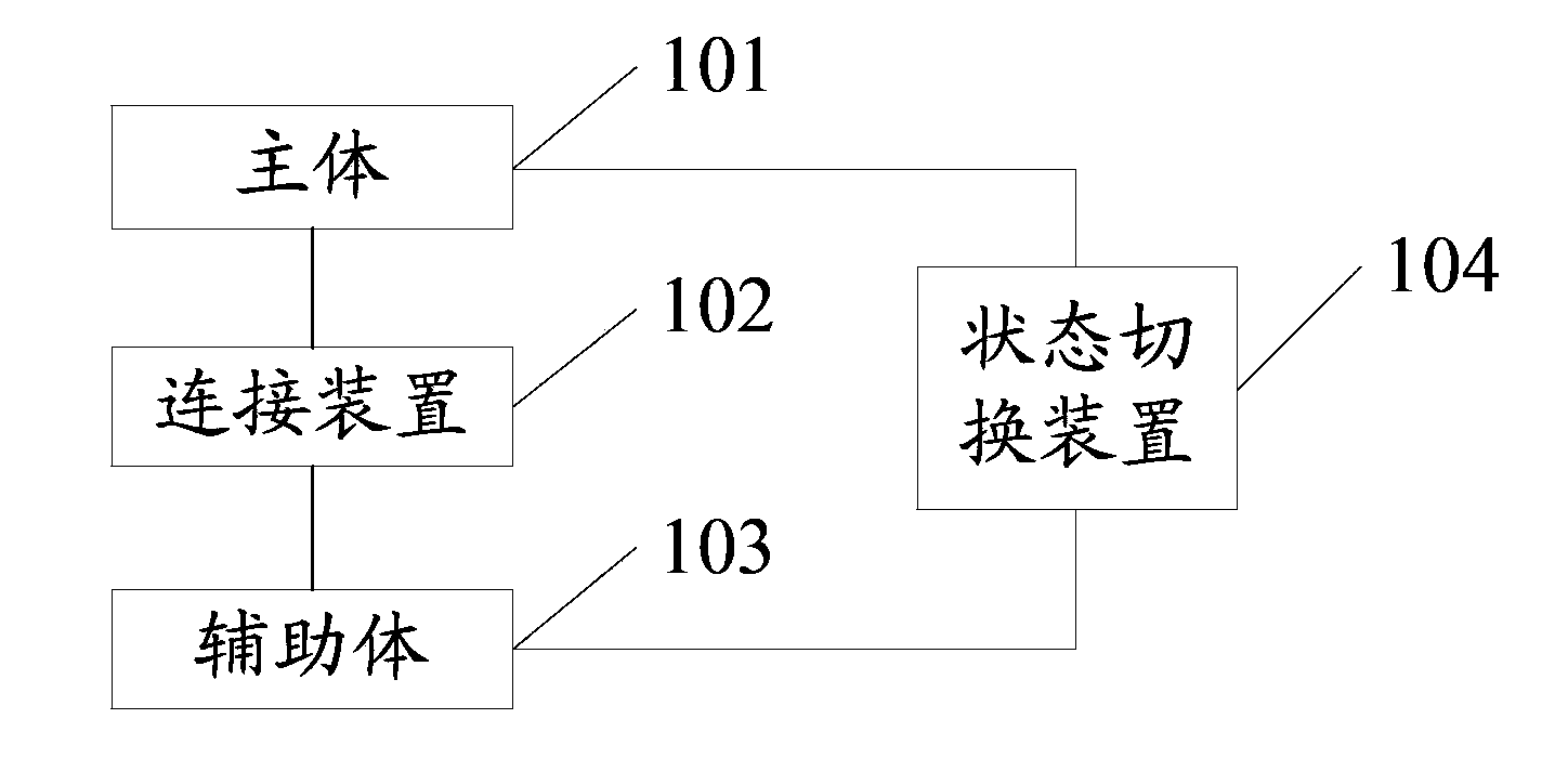
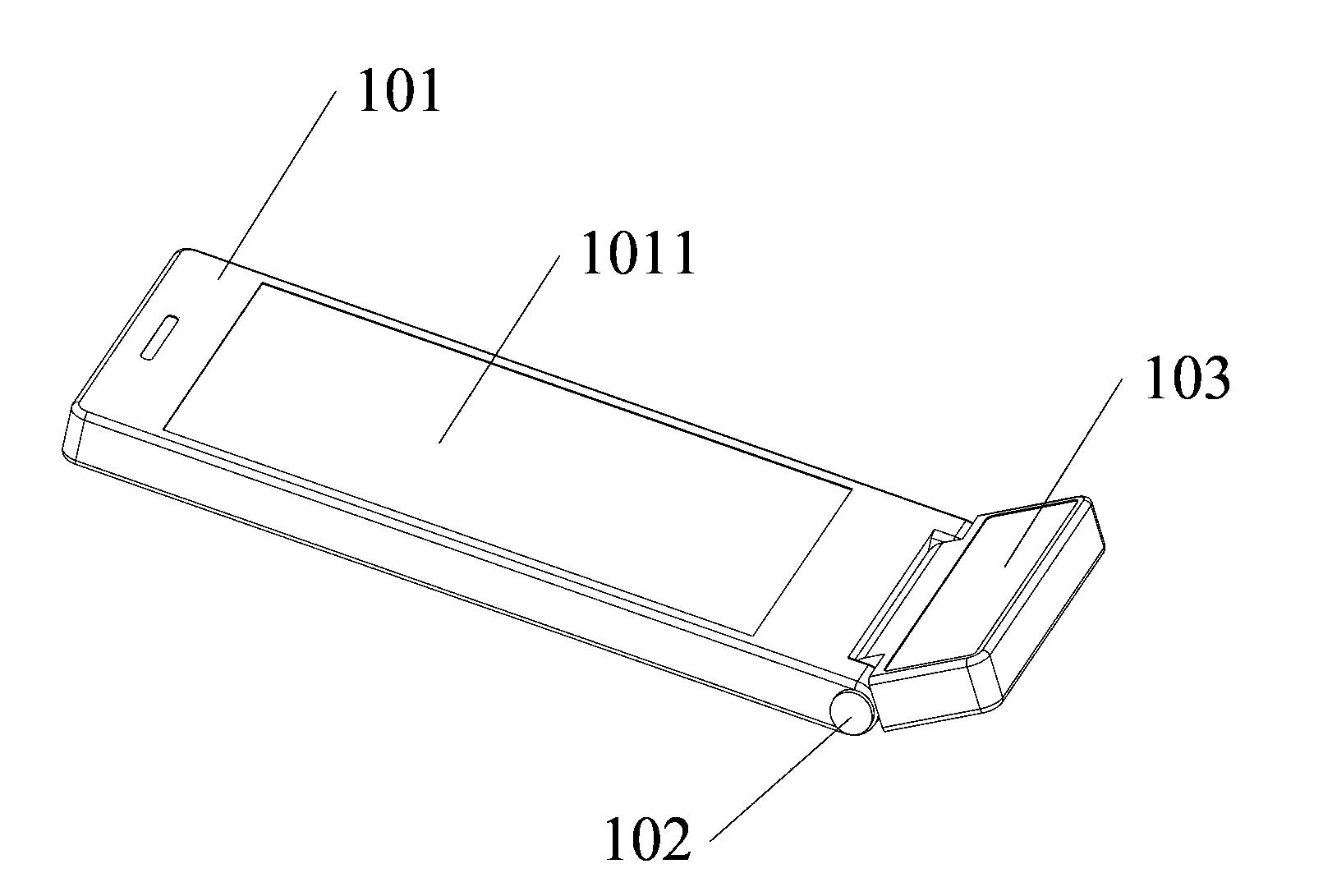
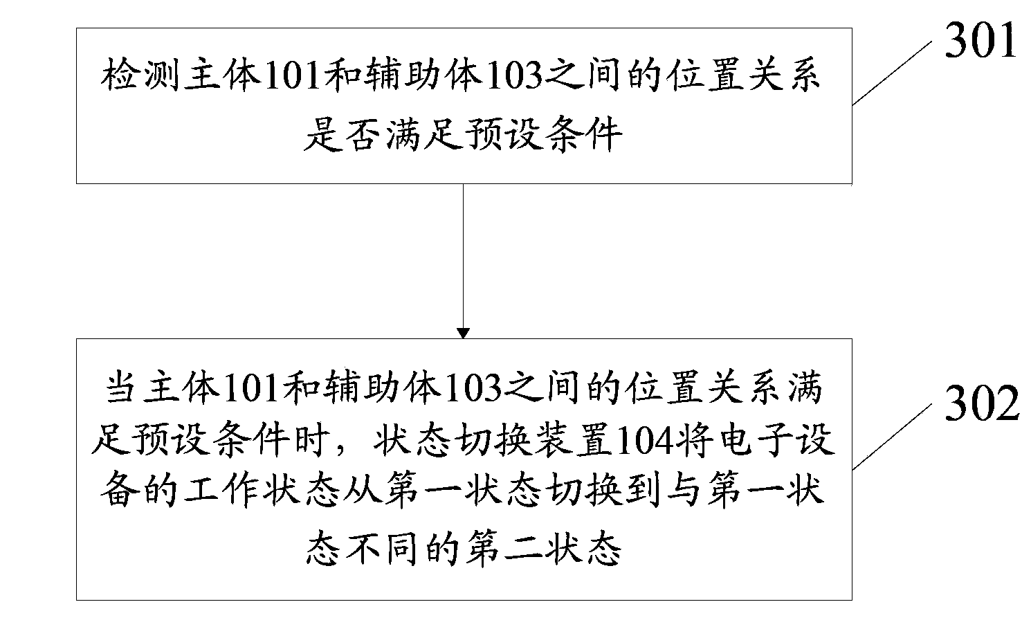
[0054] The electronic equipment includes a main body, on which a display unit is arranged, and an auxiliary body, which is rotatably connected to the main body through a connection device, and the electronic equipment also includes a state switching device, which is used for switching between the main body and the main body. When the positional relationship between the auxiliary bodies satisfies the preset condition, the working state of the electronic device is switched from the first state to a second state different from the first state. Therefore, in this embodiment, because the auxili...
PUM
 Abstract
Description
Claims
Application Information