Self-adaptation LED current ripple canceling circuit

A current ripple and circuit elimination technology, which is applied in the layout of electric lamp circuits, electric light sources, lighting devices, etc., can solve problems such as affecting LED luminous efficiency, large current ripple, and harming human health.

Active Publication Date: 2014-10-01
WUXI SI POWER MICRO ELECTRONICS
View PDF6 Cites 38 Cited by
  • Summary
  • Abstract
  • Description
  • Claims
  • Application Information

AI Technical Summary

Problems solved by technology

At the same time, the current flowing through the LED load also contains 100Hz ripple, which causes the light output by the LED load to contain 100Hz strobe
Although it is difficult for the naked eye to perceive this low-frequency flicker, the human eye will be exposed to this lighting environment for a long time, which will cause visual nerve fat

Method used


Image

  • Self-adaptation LED current ripple canceling circuit
  • Self-adaptation LED current ripple canceling circuit
  • Self-adaptation LED current ripple canceling circuit

Examples


Embodiment Construction

[0024] The present invention will be further described below in conjunction with specific drawings and embodiments.

[0025] figure 2 It is Embodiment 1 of the present invention.

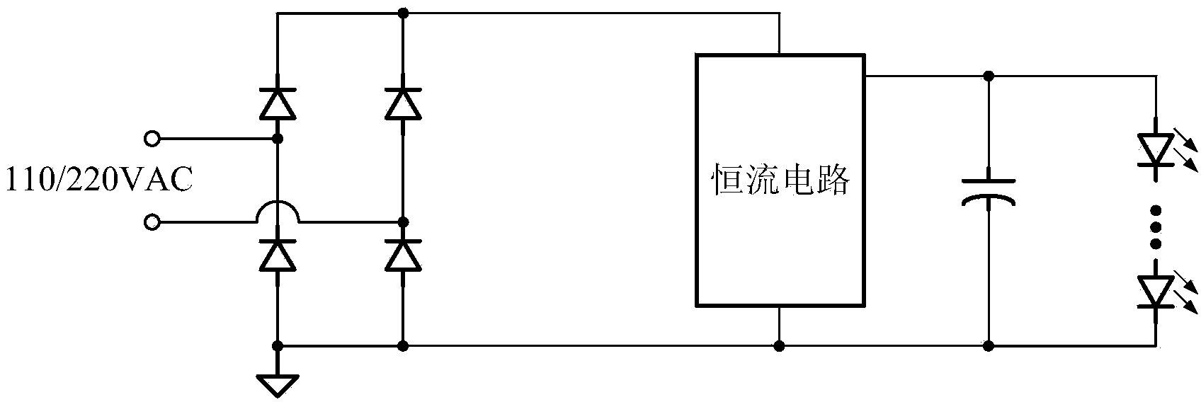
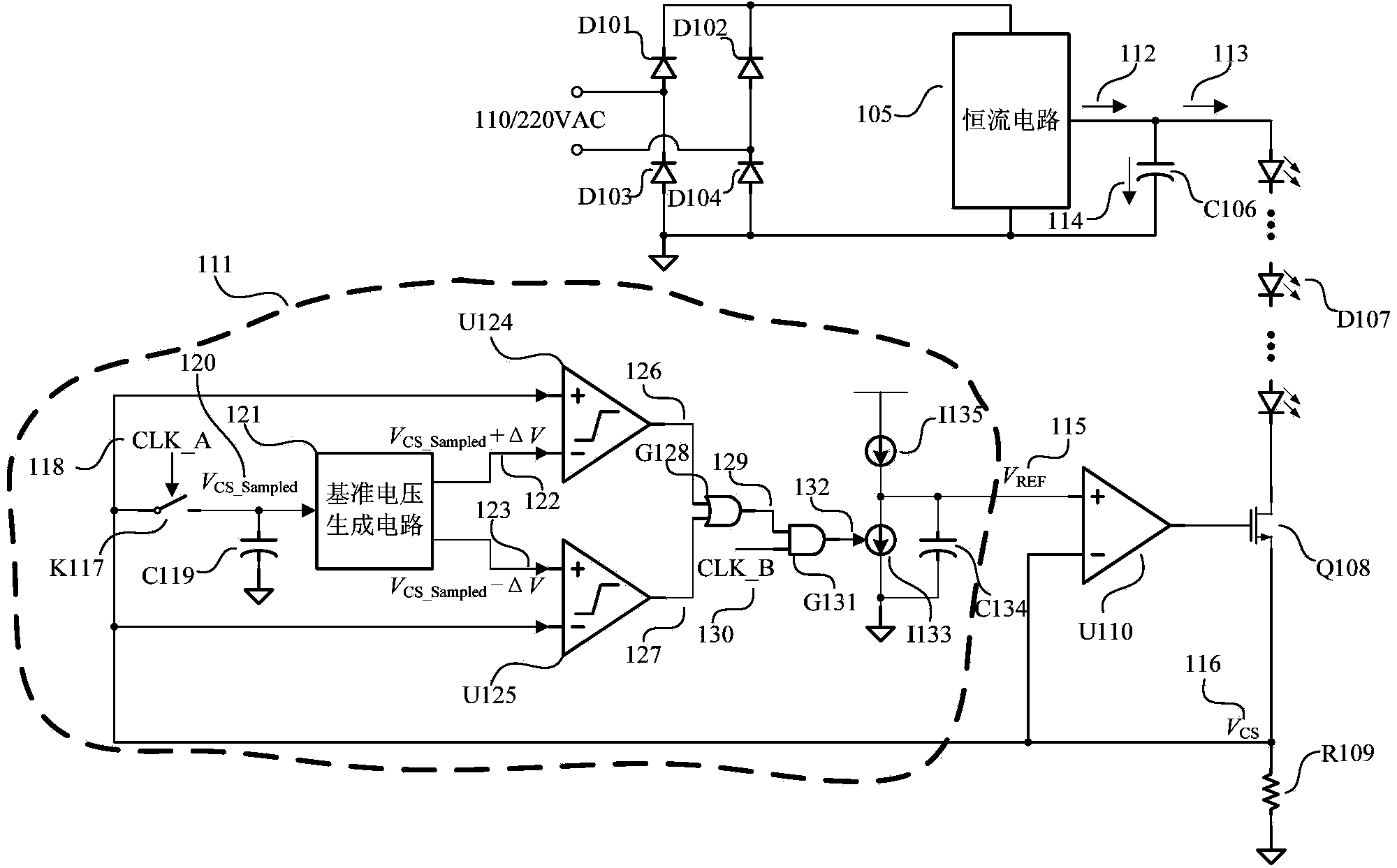
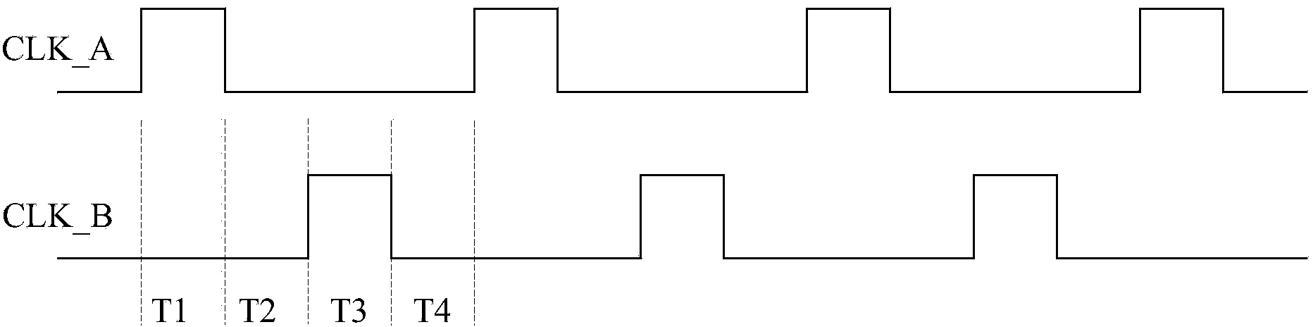
[0026] In an existing LED constant current drive circuit, the adaptive LED current ripple elimination circuit proposed by the present invention is added. Therefore, the entire LED constant current drive circuit includes rectification and filtering circuits D101, D102, D103, D104, and 105, which rectify the input AC voltage, and rectify the AC full-wave voltage with a frequency of 50 / 60Hz into an AC half-wave voltage with a frequency of 100 / 120Hz. Ripple voltage; constant current circuit 105, with power factor correction function, the output average current is constant, but there is a ripple current with a frequency of 100 / 120Hz; C106 is the output filter capacitor; D107 is a group of LED lights in series; Q108 is the power tube , can be a MOSFET. R109 is a current sampling resistor; U110 is an o...


PUM


Abstract

The invention provides a self-adaptation LED current ripple canceling circuit. The circuit comprises a power tube Q108, a current sampling resistor R109, an operational amplifier U110 and a self-adaptation reference voltage generating circuit. A drain electrode of the power tube Q108 is connected to a negative electrode of an LED load, and a source electrode of the power tube Q108 is connected to one end of the current sampling resistor R109, the inverting input end of the operational amplifier U110 and the input end of the self-adaptation reference voltage generation circuit; the output end of the self-adaptation reference voltage generating circuit is connected to the non-inverting input end of the operational amplifier U110. The output end of the operational amplifier U110 is connected with a grid electrode of the power tube Q108. The other end of the current sampling resistor R109 serves as the grounding end of the self-adaptation LED current ripple canceling circuit. The self-adaptation reference voltage generating circuit is used for automatically adjusting output voltage according to sampling voltage and controlling the operational amplifier U110 so as to control the working state of the power tube Q108 to transfer to a saturation region from a linear region. The circuit is used for canceling LED frequency flickering.

Description

technical field [0001] The invention relates to an illumination drive circuit, in particular to an LED constant current drive circuit. Background technique [0002] LED is a typical current-mode device, which requires high stability of working current. A simple schematic diagram of a traditional LED constant current drive circuit is shown in figure 1 As shown, it includes AC input source, rectifier bridge, constant current drive module, filter capacitor and LED load, and the LED load and filter capacitor are directly connected in parallel. [0003] In order to meet the requirement of high power factor, the current output by the above-mentioned constant current drive module contains power frequency ripple components. Contains 100Hz ripple. At the same time, the current flowing through the LED load also contains 100Hz ripple, which causes the light output by the LED load to contain 100Hz flicker. Although it is difficult for the naked eye to perceive this low-frequency fli...

Claims


Application Information

Patent Timeline
IPC IPC(8): H05B37/02
Inventor 励晔黄飞明赵文遐丁国华吴霖朱勤为
Owner WUXI SI POWER MICRO ELECTRONICS
Why Eureka
Try Eureka