A stamping die

A technology for stamping dies and stamping parts, which is applied in the field of molds and can solve the problems of inability to position and clamp stamping parts.

Active Publication Date: 2017-01-04
扬州宝陆汽车部件有限公司
View PDF6 Cites 0 Cited by
  • Summary
  • Abstract
  • Description
  • Claims
  • Application Information

AI Technical Summary

Problems solved by technology

(2) Existing stamping dies cannot accurately position and clamp stamping parts

Method used


Image

  • A stamping die
  • A stamping die
  • A stamping die

Examples


Embodiment Construction

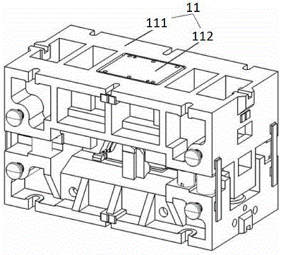
[0032] Combine below Figure 1 to Figure 7 , the present invention is further described:

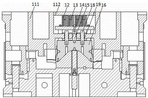
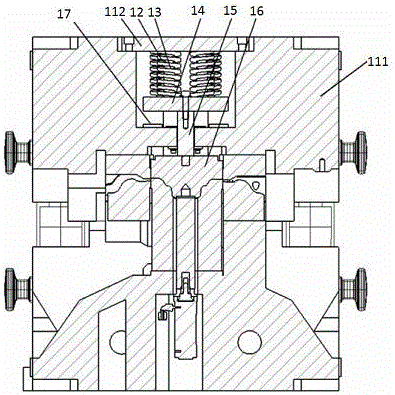
[0033] Such as Figure 1-5 As shown, the embodiment of the present invention provides an upper die of a stamping die, which includes an upper die base 11 , an elastic element 12 , a guide pin 13 , a mounting plate 14 , a dowel 15 and a pressing core 16 . Wherein, the upper mold base 11 can be an integral casting, and its bottom (the bottom refers to the side for installing the elastic element 12 after the upper mold base 11 is manufactured) has a space for installing the elastic element 12, on which there is The installation part located between the binder core 1 and the space, the installation part can specifically adopt a plate-shaped structure that can be detachably installed with the upper die base 11 .

[0034] The mounting plate 14 is installed on the mounting part, and there are generally multiple elastic elements 12, and the plurality of elastic elements 12 are installed betwee...


PUM


Abstract

The invention relates to a stamping die, comprising an upper die and a lower die. The upper die makes a dowel bar (15), a mounting plate (14) and an elastic element (12) between the pressing core (16) in sequence. One end of the cylinder (23) of the stamping part compression limit mechanism is fixed on the side wall of the lower mold base (21) through the cylinder fixed end (22), and the other end of the cylinder (23) is connected to the stamping part compression lever through the cylinder screw rod (24) One end of (25) is connected, the stamping piece pressing lever (25) is connected with the lever bracket (27) through the fulcrum bolt (26), the lever bracket (27) is fixed on the top surface of the lower mold base (21), and the stamping piece pressing lever ( The other end of 25) is the pressing part of the stamping part and has a U-shaped passage groove (251). One end of the positioning rod (29) is fixed on the top surface of the lower mold base (21), and the other end of the positioning rod (29) is inserted into the U. In the type passage groove (251), the positioning rod (29) passes through the positioning hole on the stamping part.

Description

technical field [0001] The invention relates to a die, in particular to a stamping die. Background technique [0002] With the rapid development of the automobile industry, the application of stamping dies has become more and more extensive. During the stamping process, the elastic elements installed in the upper die provide sufficient pressing force to prevent the movement of the sheet during the stamping process and cause the plate The problem of lower precision and lower quality of stamping parts. [0003] The currently commonly used stamping dies mainly include an upper die base, a side pin, a lower die base, a pressing core, a square spacer, an elastic element, a spring guide pin and a guide plate. Wherein the upper mold base is an integral casting structure, the side pin passes through the side wall of the upper mold base, and is fixed on the upper mold base through the fixing plate, and the side pin cooperates with the groove on the pressing core to control the strok...

Claims


Application Information

Patent Timeline
Patent Type & Authority Patents(China)
IPC IPC(8): B21D37/10B21D43/00
Inventor 王娟姚和中
Owner 扬州宝陆汽车部件有限公司
Why Eureka
Try Eureka