
Injection mold and angle ejecting mechanism thereof

A technology of inclined roof mechanism and injection mold, which is applied in the field of injection molds, can solve problems such as movement jamming, deformation of inclined ejector rod, and reduced movement reliability of inclined ejector mechanism, so as to improve movement reliability, not easily deform, and ensure movement Effect

Inactive Publication Date: 2014-10-22
SHENZHEN SILVER BASIS TECH
View PDF2 Cites 7 Cited by
  • Summary
  • Abstract
  • Description
  • Claims
  • Application Information

AI Technical Summary

Problems solved by technology

For plastic products with complex structures, when designing the inclined ejection mechanism in the injection mold corresponding to its structure, it is necessary to increase the demoulding angle on the basis of the original oblique ejection angle. Therefore, when the mold is repeatedly opened , the inclined ejector mechanism will be subjected to a lateral force perpendicular to the inclined ejection direction as a whole during the comprehensive movement process of inclined ejection and angle demoulding, especially the inclined ejector rod of the inclined ejector mechanism, because the inclined ejector rod It is a rod-shaped structure, and most of it is suspended in the mold, and there is basically no support. Therefore, the inclined ejector rod itself mainly bears and offsets the lateral force, so that the inclined ejector rod is easy to deform, and the inclined ejector mechanism is a high-precision matching mechanism. , the slight deformation of the lifter rod will cause the movement of the lifter mechanism to be unsmooth, and the phenomenon of motion jamming will occur, which will reduce the reliability of the movement of the lifter mechanism

Method used


Image

  • Injection mold and angle ejecting mechanism thereof
  • Injection mold and angle ejecting mechanism thereof
  • Injection mold and angle ejecting mechanism thereof

Examples


Embodiment Construction

[0023] The invention provides an inclined jack mechanism, which eliminates the lateral force on the inclined jack rod, makes the inclined jack rod not easily deformed, and improves the reliability of the movement of the inclined jack mechanism.

[0024] The present invention also provides an injection mold using the above-mentioned inclined top mechanism, which ensures that the inclined top mechanism can move more smoothly when the injection mold is being injected, and improves the working reliability of the injection mold.

[0025] The following will clearly and completely describe the technical solutions in the embodiments of the present invention with reference to the accompanying drawings in the embodiments of the present invention. Obviously, the described embodiments are only part of the embodiments of the present invention, not all of them. Based on the embodiments of the present invention, all other embodiments obtained by persons of ordinary skill in the art without ma...


PUM


Abstract

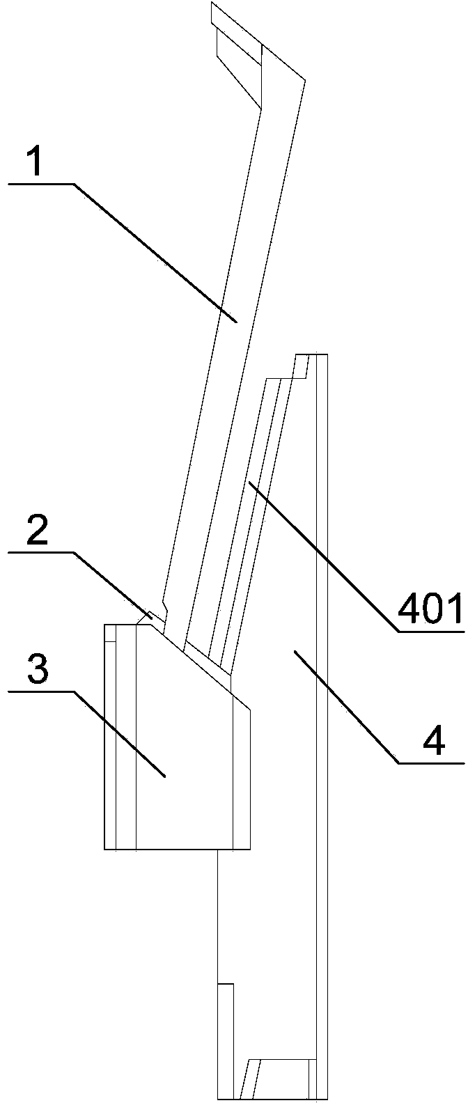
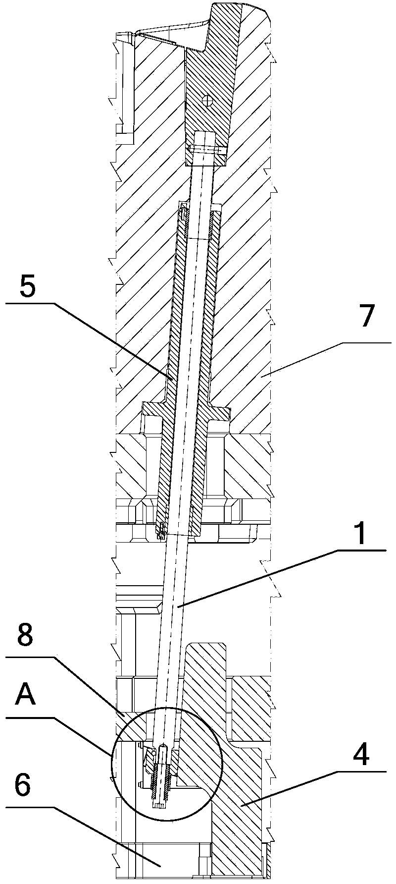
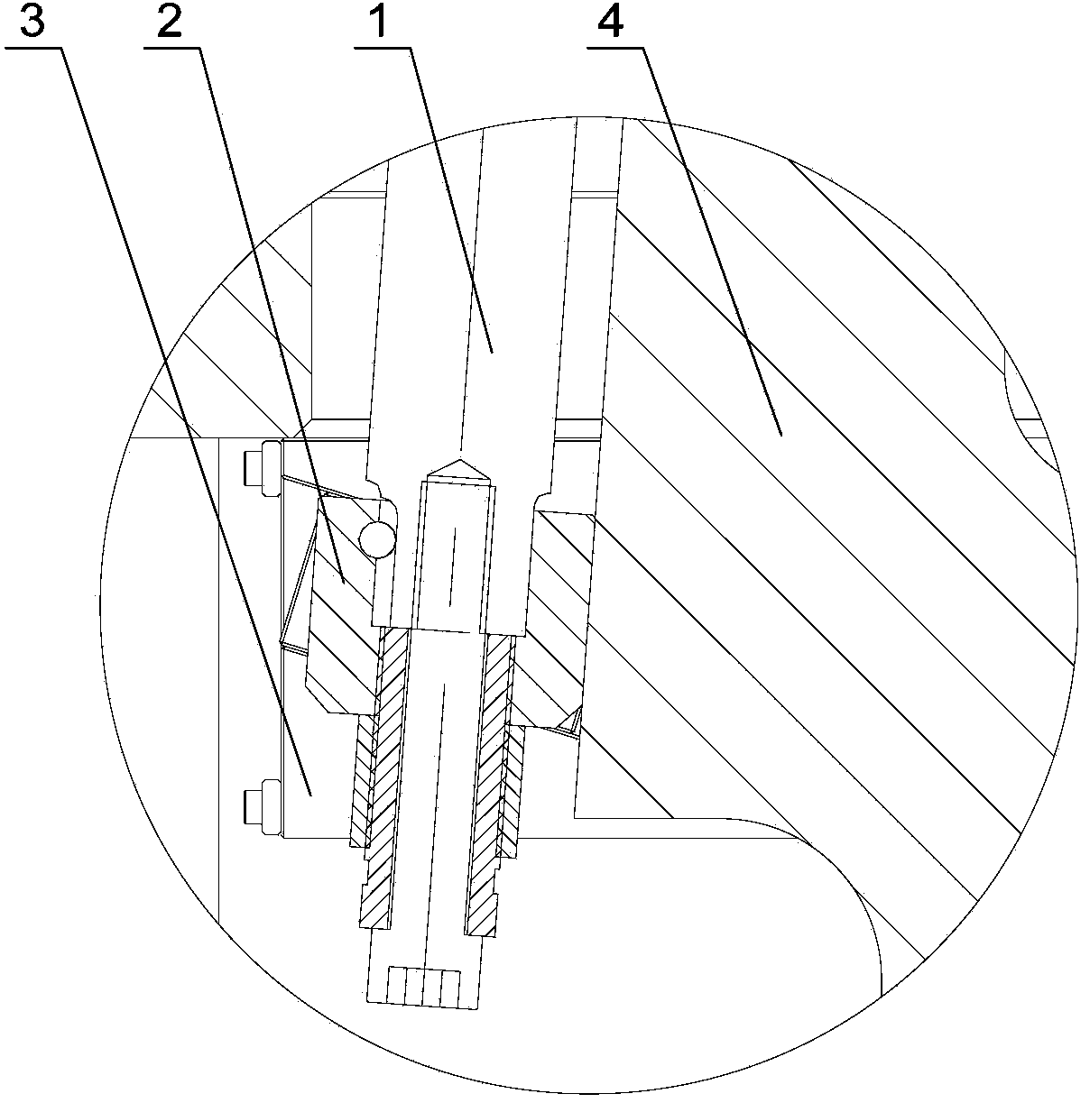
The invention discloses an angle ejecting mechanism. The angle ejecting mechanism comprises an angle ejecting rod, an angle ejecting base, an angle ejecting base slide block and a support guide block, wherein the angle ejecting rod and the angle ejecting base slide block are fixed; the angle ejecting base slide block and the angle ejecting base are connected with each other in a sliding mode; the support guide block is fixedly connected with a base plate of an injection mold, and is provided with a first guide structure which is parallel to the ejection direction of the angle ejecting rod; the angle ejection base slide block is provided with a second guide structure in sliding fit with the first guide structure. The angle ejecting mechanism is additionally provided with the support guide block, so that the lateral force formed by the angle ejecting mechanism in the ejecting process is transferred to the support guide block by the angle ejecting base slide block via the sliding fit between the first guide structure and the second guide structure; the lateral force borne by the angle ejecting rod is offset by the counterforce generated by the support guide block, so that the angle ejecting rod is unlikely to deform; the motion smoothness of the angle ejecting mechanism is ensured; the motion reliability of the angle ejecting mechanism is improved. The invention also discloses the injection mold applying the angle ejecting mechanism.

Description

technical field [0001] The invention relates to the technical field of injection molds, in particular to an inclined roof mechanism. It also relates to an injection mold using the above-mentioned inclined top mechanism. Background technique [0002] The inclined top mechanism is a mechanism used to shape the inner barb of the product and eject it in the injection mold. For plastic products with complex structures, when designing the inclined ejection mechanism in the injection mold corresponding to its structure, it is necessary to increase the demoulding angle on the basis of the original inclined ejection angle. Therefore, when the mold is repeatedly opened , the inclined ejector mechanism will be subjected to a lateral force perpendicular to the inclined ejection direction as a whole during the comprehensive movement process of inclined ejection and angle demoulding, especially the inclined ejector rod of the inclined ejector mechanism, because the inclined ejector rod ...

Claims


Application Information

Patent Timeline
Patent Type & Authority Applications(China)
IPC IPC(8): B29C45/40B29C45/26
CPCB29C45/4005
Inventor 胡作寰高国利李芳刘勇黄清刚黄国民
Owner SHENZHEN SILVER BASIS TECH
Learn More