Light guide board and backlight module
A technology of backlight module and light guide plate, which is applied in the direction of light guide, optics, optical components, etc., can solve the problems of increasing the production cost of backlight module and so on.
- Summary
- Abstract
- Description
- Claims
- Application Information
AI Technical Summary
Problems solved by technology
Method used
Image

Examples
Embodiment Construction
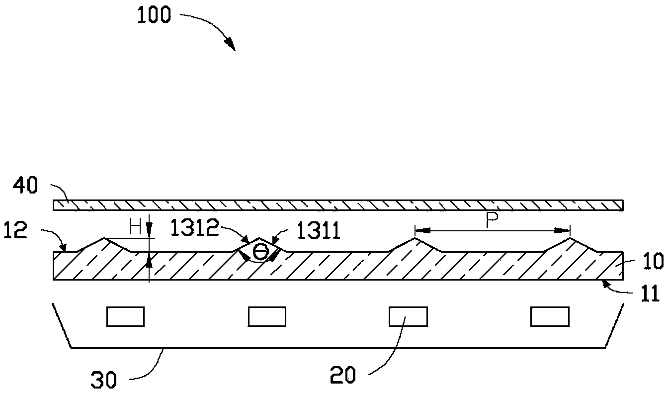
[0014] see figure 1 and figure 2 , the backlight module 100 provided by the first embodiment of the present invention includes a light guide plate 10 , a plurality of light sources 20 and a reflective sheet 30 .
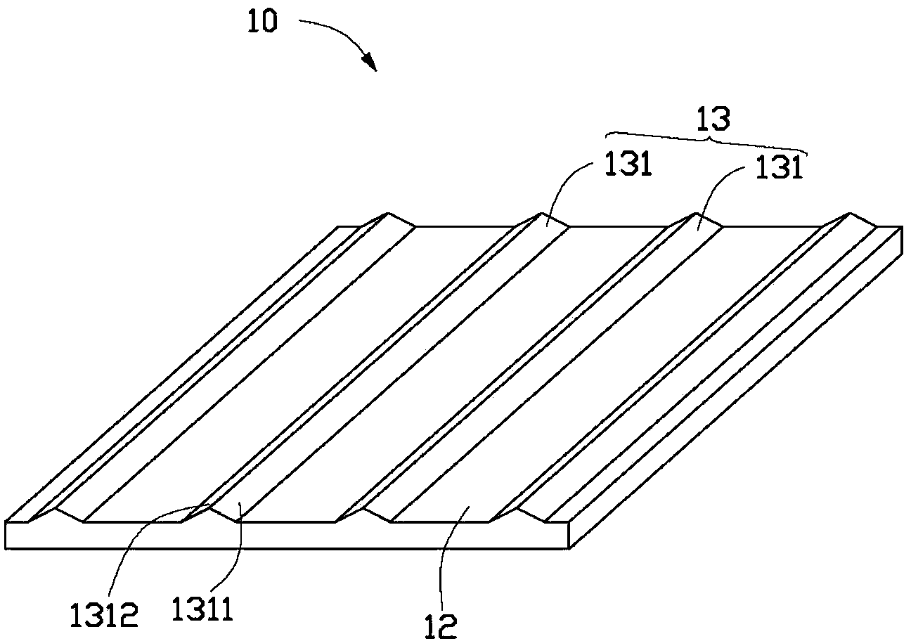
[0015] The light guide plate 10 is disposed above the plurality of light sources 20 , that is, the light guide plate 10 is opposite to the plurality of light sources 20 . The light guide plate 10 is roughly plate-shaped, and has a light-incident surface 11 and a light-exit surface 12 opposite to each other. The light incident surface 11 and the light exit surface 12 are arranged parallel to each other. The light incident surface 11 is opposite to the light source 20 .
[0016] The light guide plate 10 is made of a light-transmitting material, and the material of the light guide plate 10 can be polycarbonate (PC), polymethyl methacrylate (PMMA), methyl methacrylate, styrene copolymer ( MS), polyethylene terephthalate (PETG), polystyrene (PS) or a mixture of two o...
PUM
| Property | Measurement | Unit |
|---|---|---|
| Angle | aaaaa | aaaaa |
| Angle | aaaaa | aaaaa |
Abstract
Description
Claims
Application Information
 - R&D
- Intellectual Property
- Life Sciences
- Materials
- Tech Scout
- Unparalleled Data Quality
- Higher Quality Content
- 60% Fewer Hallucinations
Browse by: Latest US Patents, China's latest patents, Technical Efficacy Thesaurus, Application Domain, Technology Topic, Popular Technical Reports.
© 2025 PatSnap. All rights reserved.Legal|Privacy policy|Modern Slavery Act Transparency Statement|Sitemap|About US| Contact US: help@patsnap.com