Phosphor and luminescence device
A technology of light-emitting devices and phosphors, which is applied in the direction of light-emitting materials, semiconductor devices, electrical components, etc., and can solve problems such as the decrease of luminance and color rendering, poor heat resistance of crystals, and unpopularity of commercial use.
- Summary
- Abstract
- Description
- Claims
- Application Information
AI Technical Summary
Problems solved by technology
Method used
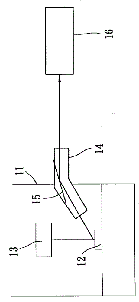
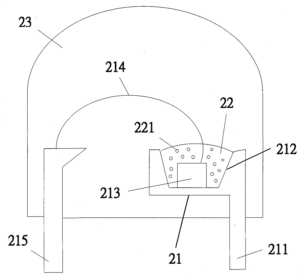
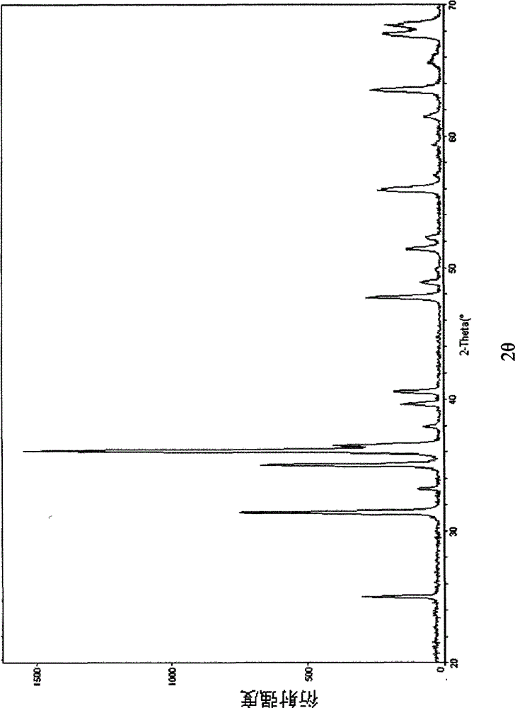
Image

Examples
Synthetic example 1
[0070] Prepare the required calcium metal (3N7), strontium metal (4N), magnesium metal (2N) and barium metal (2N), pulverize them and place them in a pure nitrogen atmosphere to directly sinter them to form nitrides. The reaction conditions are 750℃. , 700°C, 600°C, and 700°C for 24 hours. Calcium nitride (Ca 3 N 2 ), strontium nitride (Sr 3 N 2 ), magnesium nitride (Mg 3 N 2 ) and barium nitride (Ba 3 N 2 )compound of.
Embodiment 1
[0072] Preparation of Ca synthesized in Synthesis Example 1 3 N 2 , Sr 3 N 2 , Mg 3 N 2 and AlN(3N), Si 3 N 4 (3N), Eu 2 O 3 (4N), according to Ca 3 N 2 Take 0.445 / 3 mole, Sr 3 N 2 Take 0.542 / 3 mole, Mg 3 N 2 Take 0.005 / 3 mole, take 1 mole of AlN, Si 3 N 4 Take 1 / 3 mole, Eu 2 O 3 Each raw material powder was weighed at a ratio of 0.008 / 2 mol, and mixed using a mortar in a glove box under a nitrogen atmosphere. The molar ratio of each element in the raw material mixed powder is shown in Table 1. The mixed powder of the aforementioned raw materials is placed in a boron nitride crucible, and the crucible is placed in a high-temperature furnace. The atmosphere in the furnace is an environment of high-purity nitrogen, and the gas flow rate is 80 liters / min. To 1500°C, after sintering at 1500°C for 12 hours, drop to room temperature at a cooling rate of 10°C / min, and go through the steps of pulverization, ball milling, secondary washing with water, filtration, dry...
Embodiment 2~5
[0073] Examples 2 to 5, Comparative Example 1
[0074] The molar ratio of each element in the raw material mixed powder is adjusted as in Table 1, and the remaining steps are the same as in Example 1. The rest of the physical property test results are listed in Table 1-A. It can be seen from Table 1-A that under the same chromaticity, the phosphor containing calcium, strontium and the content of magnesium and / or barium within the specific range of the present invention has a higher luminous brightness than the content of magnesium and / or barium in the present invention. For phosphors outside the specific range of the invention, the brightness difference can reach up to 8%. The source of barium element in Tables 1 to 6 is barium nitride (Ba 3 N 2 ).
PUM
| Property | Measurement | Unit |
|---|---|---|
| particle size | aaaaa | aaaaa |
| particle size | aaaaa | aaaaa |
| particle size | aaaaa | aaaaa |
Abstract
Description
Claims
Application Information