
Phosphor and luminescence device

A light-emitting device and phosphor technology, which is applied in the direction of light-emitting materials, semiconductor devices, electrical components, etc., can solve the problems of insufficient luminance of phosphors, poor heat resistance of crystals, decline in luminance and color rendering, etc.

Active Publication Date: 2012-05-16
DENKA CO LTD
View PDF6 Cites 6 Cited by
  • Summary
  • Abstract
  • Description
  • Claims
  • Application Information

AI Technical Summary

Problems solved by technology

However, Sr 2 Si 5 N 8 : Due to the poor heat resistance of the crystal itself, the Eu phosphor has the disadvantages of reduced luminance and color rendering when used for a long time; although the Sialon phosphor itself has no durability problem, the luminance of the phosphor is obviously insufficient, and it is not commercially available. not popular

Method used

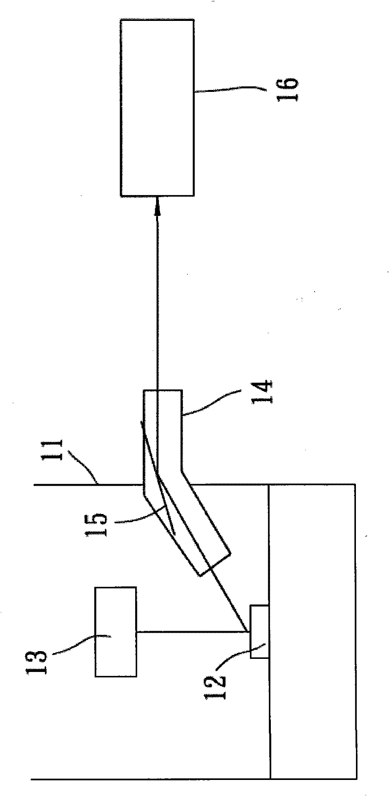
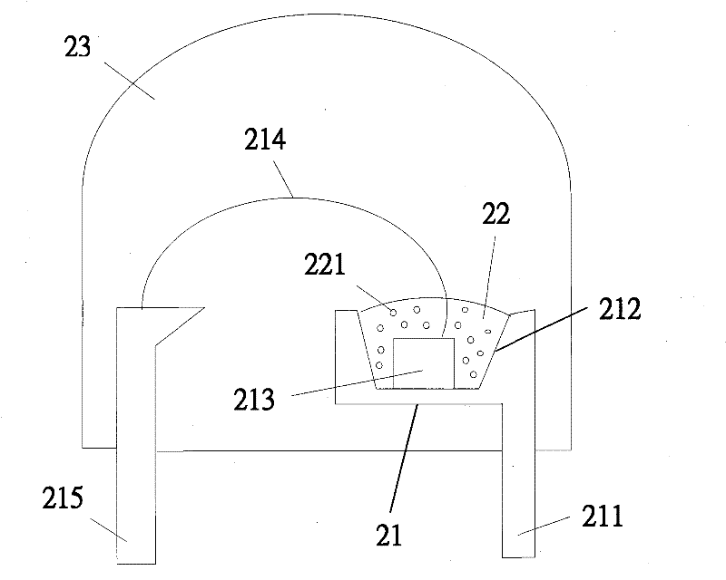
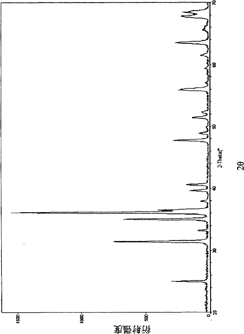

Image

  • Phosphor and luminescence device
  • Phosphor and luminescence device
  • Phosphor and luminescence device

Examples


Synthetic example 1

[0070] Prepare the required calcium metal (3N7), strontium metal (4N), magnesium metal (2N) and barium metal (2N), after crushing, place them in a pure nitrogen atmosphere and directly fire them to form nitrides. The reaction conditions are 750°C , 700°C, 600°C, and 700°C for 24 hours. Calcium nitride (Ca 3 N 2 ), strontium nitride (Sr 3 N 2 ), magnesium nitride (Mg 3 N 2 ) and barium nitride (Ba 3 N 2 )compound of.

Embodiment 1

[0072] Prepare the Ca synthesized in Synthesis Example 1 3 N 2 、Sr 3 N 2 , Mg 3 N 2 And AlN(3N), Si 3 N 4 (3N), Eu 2 o 3 (4N), according to Ca 3 N 2 Take 0.445 / 3 mole, Sr 3 N 2 Take 0.542 / 3 mole, Mg 3 N 2 Take 0.005 / 3 mole, AlN take 1 mole, Si 3 N 4 Take 1 / 3 mole, Eu 2 o 3 Each raw material powder was weighed at a ratio of 0.008 / 2 mol, and mixed using a mortar in a glove box under a nitrogen atmosphere. The molar ratio of each element in the raw material mixed powder is shown in Table 1. Put the mixed powder of the aforementioned raw materials into a boron nitride crucible, and put the crucible into a high-temperature furnace. The atmosphere in the furnace is an environment of high-purity nitrogen. The gas flow rate is 80 liters / minute, and the temperature is raised at a heating rate of 10°C / min. After firing at 1500°C for 12 hours, the temperature is lowered to room temperature at a cooling rate of 10°C / min, and through steps such as crushing, ball milling,...

Embodiment 2~5

[0073] Embodiment 2~5, comparative example 1

[0074] The molar ratio of each element in the raw material mixed powder is adjusted as shown in Table 1, and the rest of the steps are the same as in Example 1. The rest of the physical property test results are listed in Table 1-A. It can be seen from Table 1-A that under the same chromaticity, the luminous luminance of phosphors containing calcium, strontium and the content of magnesium and / or barium within the specified range of the present invention is higher than that of the phosphors with the content of magnesium and / or barium in this invention. For phosphors outside the specified range, the difference in luminance can reach up to 8%. The source of barium element in tables 1-6 is the barium nitride (BaN) of synthesis example 1 3 N 2 ).


PUM


Abstract

The invention provides phosphor which comprises a component with a composition as shown in formula (I), wherein M is selected from a group composed of beryllium and zinc; A is selected from a group composed of aluminium, gallium, indium, scandium, yttrium, lanthanum, gadolinium, and lutetium; B is selected from a group composed of silicon, germanium, tin, titanium, zirconium, and hafnium ; 0<p<1, 0<q<1, 0<=m<1, 0<=t<=0.3, 0.00001<=r<=0.1, a=1, 0.8<=b<=1.2, 2.7<=n<=3.1; the phosphor comprises 20-1500 ppm of magnesium and / or 40-5000 ppm of barium. Through the adjustment of the ratios of the elements forming the phosphor and through the cooperative control of the concentrations of magnesium and barium forming the phosphor within a certain range, the phosphor is obtained with high luminance in a range of 600-680 nm; in addition, the invention also provides a luminescence device with high luminance. CapSrqMm-Aa-Bb-Ot-Nn:Eur (I).

Description

technical field [0001] The present invention relates to a nitride phosphor used in lighting units such as displays, backlights for liquid crystals, fluorescent lamps, and light emitting diodes. The present invention relates to the composition of the nitride phosphor and a light-emitting device using the phosphor. Background technique [0002] In recent years, light-emitting devices that use semiconductors to emit light have been widely used, especially light-emitting diodes have been successfully developed. This light-emitting device has high luminous efficiency, small size, and low power consumption. It can be used as a variety of light sources due to the advantages of power and low cost. The semiconductor light-emitting device includes a semiconductor light-emitting component and a phosphor. The phosphor can absorb and convert the light emitted by the semiconductor light-emitting component, and the light emitted by the semiconductor light-emitting component and the light ...

Claims


Application Information

Patent Timeline
IPC IPC(8): C09K11/64C09K11/80H01L33/50
Inventor 庄渊仁温正雄林志龙
Owner DENKA CO LTD
Features
  • Generate Ideas
  • Intellectual Property
  • Life Sciences
  • Materials
  • Tech Scout
  • Unparalleled Data Quality
  • Higher Quality Content
  • 60% Fewer Hallucinations
Learn More