Integrated flange for mutual inductor

An integrated, transformer technology, applied in the direction of inductors, transformers, transformer/inductance components, etc., can solve problems such as poor sealing performance

Inactive Publication Date: 2014-10-22
HENGYANG HUARUI ELECTRIC
View PDF0 Cites 0 Cited by
  • Summary
  • Abstract
  • Description
  • Claims
  • Application Information

AI Technical Summary

Problems solved by technology

[0002] In the traditional technology, most of the transformer flanges use two flanges with the same hole diameter but different outer diameters to be connected by screws to form a structure with bosses; however, gaps will appear between the two flanges after long-term use, and their sealing performance is poor

Method used


Image

  • Integrated flange for mutual inductor

Examples


Embodiment Construction

[0007] The present invention will be further described below in conjunction with the accompanying drawings and embodiments.

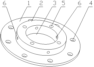
[0008] Such as figure 1 As shown, a transformer integrated flange includes a flange body 1, the flange body 1 is disc-shaped, and a circular boss 2 is provided in the middle, and a circular boss 2 is provided in the center of the flange body 1. Through hole 3 is evenly provided with a plurality of threaded through holes 4 on the circumference of described flange body 1, is evenly provided with a plurality of threaded through holes 5 on the upper surface of described circular boss 2, and its side is provided with at least Four pairwise symmetrical threaded holes 6 .


PUM


Abstract

The invention relates to connecting pieces, in particular to an integrated flange for a mutual inductor. The integrated flange comprises a flange body which is of a disk shape. The middle of the flange body is provided with a circular boss. The center of the flange body is provided with a circular through hole. The circumference of the flange body is evenly provided with multiple threaded through holes. The upper surface of the circular boss is evenly provided with multiple threaded through holes. The side face of the circular boss is provided with at least four threaded holes which are symmetrically arranged in pairs. The integrated flange is formed in a one-off casting mode and can still keep good sealing performance after long-term use.

Description

technical field [0001] The invention relates to a connecting piece, in particular to a transformer integral flange. Background technique [0002] In the traditional technology, most of the transformer flanges use two flanges with the same hole diameter but different outer diameters connected by screws to form a structure with bosses; however, gaps will appear between the two flanges after long-term use, and their sealing performance is poor . Contents of the invention [0003] The technical problem to be solved by the present invention is to overcome the above-mentioned deficiencies in the prior art and provide a transformer integral flange with good sealing performance. [0004] The technical solution of the present invention is: a transformer integrated flange, including a flange body, the flange body is disc-shaped, with a circular boss in the middle, and a circular boss in the center of the flange body. Through holes, a plurality of threaded through holes are evenly ...

Claims


Application Information

Patent Timeline
Patent Type & Authority Applications(China)
IPC IPC(8): H01F38/20H01F27/00
Inventor 曾祥顺戈济民
Owner HENGYANG HUARUI ELECTRIC
Why Eureka
Try Eureka