A continuous punching device for straight pipe

A punching device and pipe technology, applied in the directions of feeding device, storage device, positioning device, etc., can solve the problems of low punching efficiency, inability to realize continuous punching, complex structure, etc., and achieve the effect of improving punching efficiency

Active Publication Date: 2017-06-27
冠达星股份有限公司
View PDF1 Cites 0 Cited by
  • Summary
  • Abstract
  • Description
  • Claims
  • Application Information

AI Technical Summary

Problems solved by technology

[0002] Holes are processed on the pipe wall of the pipe, usually by drilling or milling on the machine tool, and also by punching. For example, the Chinese patent with publication number CN101708520B discloses a pipe punching device , but its structure is complicated, and continuous punching cannot be realized, and the punching efficiency is low

Method used


Image

  • A continuous punching device for straight pipe
  • A continuous punching device for straight pipe
  • A continuous punching device for straight pipe

Examples


Embodiment Construction

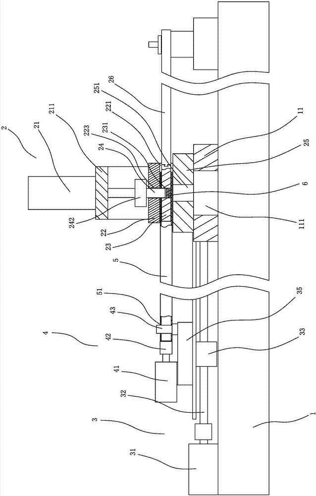
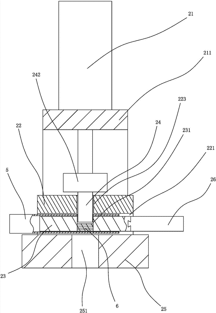
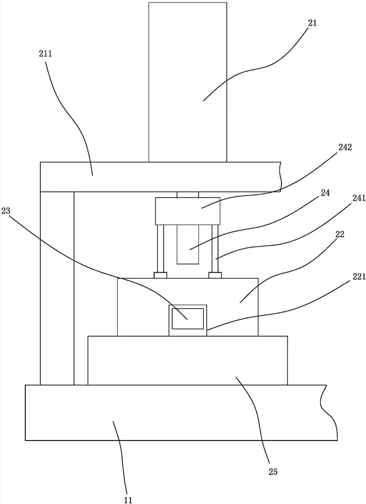
[0020] refer to figure 1 , figure 2 and image 3 As shown, taking a straight pipe with a rectangular cross section as an example, a continuous punching device for a straight pipe includes a base 1, a punching mechanism 2, a sliding seat 35, a lateral movement mechanism 3, a clamping mechanism 4 and a control device, the base 1 is provided with a plurality of punching mechanisms 2 arranged longitudinally at intervals, and the corresponding sliding seat 35 is provided with a plurality of clamping mechanisms 4 arranged longitudinally at intervals. Clamp mechanism 4 is connected, is used for controlling each mechanism to coordinate work.

[0021] The punching mechanism 2 is arranged in the middle of the base 1, including a mold base, a mandrel 23 and a punching mechanism. A through hole 221 extending transversely is formed on the side of the mold base, and a first punching hole 223 communicating with the through hole 221 is formed on the top surface. , the bottom surface is fo...


PUM


Abstract

A continuous punching device for linear pipes, comprising a base, a punching mechanism arranged on the base, a sliding seat arranged on the base capable of moving horizontally and horizontally, a lateral movement mechanism for driving the sliding seat to move laterally, and a sliding seat arranged on the sliding seat The clamping mechanism used to clamp one end of the straight pipe, and the control device connected with the punching mechanism and the lateral movement mechanism respectively. The punching mechanism includes a mold base, a mandrel and a punching mechanism. There is a through hole that extends horizontally and can be inserted into by a straight pipe, the top surface is formed with a first punching hole that communicates with the through hole, and the bottom surface is formed with a discharge hole that is connected with the through hole; the core mold is set on the In the through hole of the mold base, a second punching hole opposite to the first punching hole is formed on the mandrel; the punching mechanism includes a punch that can move up and down relative to the first and second punching holes and a driving member that drives the punch to move up and down , the present invention has the advantages of simple structure, convenient operation and high punching efficiency.

Description

technical field [0001] The invention relates to a continuous punching device for straight pipes, which is used for continuous punching on straight pipes. Background technique [0002] Holes are processed on the pipe wall of the pipe, usually by drilling or milling on the machine tool, and also by punching. For example, the Chinese patent with publication number CN101708520B discloses a pipe punching device , but its structure is complicated, and continuous punching cannot be realized, and the punching efficiency is low. Contents of the invention [0003] The object of the present invention is to provide a continuous punching device for linear pipes with simple structure, convenient operation and high punching efficiency, aiming at the deficiencies of the prior art. [0004] The purpose of the present invention is achieved through the following technical solutions: [0005] A continuous punching device for linear pipes, comprising a base, a punching mechanism arranged on ...

Claims


Application Information

Patent Timeline
Patent Type & Authority Patents(China)
IPC IPC(8): B21D28/28B21D28/34B21D43/00B21D43/13
Inventor 杨建明
Owner 冠达星股份有限公司
Why Eureka
Try Eureka