Splicing clip for bellows units and application thereof

A corrugated pipe and compatible technology, applied in the field of splicing clips for corrugated pipe units, can solve problems such as the separation of arc-shaped corrugated pipe units due to gravity, the threat to the construction safety of dismantling personnel, and the large size of corrugated pipes, so as to achieve rapid alignment and improve Installation splicing efficiency, increase the effect of quick alignment and fixation

Active Publication Date: 2014-11-05
HEBEI TENGSHIDA METAL STRUCTURE
View PDF8 Cites 2 Cited by
  • Summary
  • Abstract
  • Description
  • Claims
  • Application Information

AI Technical Summary

Problems solved by technology

[0003] However, the existing corrugated pipes used in culvert construction are large in size, so the corrugated pipes are mostly assembled from arc-shaped corrugated pipe units
For example, when assembling corrugated pipes for culverts, it is necessary to splice the arc-shaped corrugated pipe units one by one. However, during the splicing process, it is necessary to align according to the corrugated structure of the corrugated pipes. The alignment process is time-consuming and laborious, and sometimes it must be done with the help of external equipment After lifting and aligning, if the installation alignment is not tight, the connected arc bellows unit will be separated by gravity, posing a threat to the construction safety of dismantling personnel

Method used


Image

  • Splicing clip for bellows units and application thereof
  • Splicing clip for bellows units and application thereof
  • Splicing clip for bellows units and application thereof

Examples


Embodiment 1

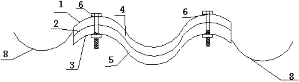
[0029] Such as figure 2 , 3 shown.

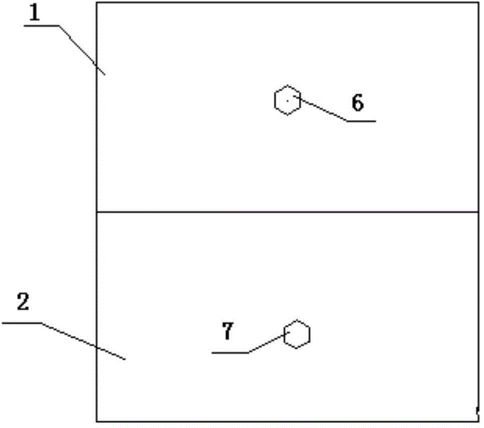
[0030] A bellows unit splicing clip, comprising three first guard plates 1, a support plate 2, and a second guard plate 3 arranged adjacent to each other. The first recess 4, the second guard plate 3 and the support plate 2 form the second recess 5 that accommodates the edge of the bellows unit; Mounting holes 6 are provided, and the mounting holes coaxially penetrating through the first guard plate, the support plate and the second guard plate form a group of mounting holes.

[0031] The length of the support plate 2 is greater than the first guard plate 1 and the second guard plate 3, and the end of the support plate 2 protrudes from the first guard plate 1 and the second guard plate 3, and at the protruding part of the support plate 2 A fixing hole 7 adapted to the splicing hole of the bellows unit 8 is provided on the top.

[0032] The number of the fixing hole 7 is one.

[0033] The arc shapes of the first guard plate 1 , the sup...

Embodiment 2

[0036] Such as Figure 4 shown.

[0037] A bellows unit splicing clip as described in Embodiment 1, the difference is that the number of the fixing holes 7 is two. Two sets of mounting holes are provided on the splicing clip of the bellows unit 8 .

Embodiment 3

[0039] A method for splicing bellows by using the bellows unit splicing clips as described in Embodiments 1 and 2, comprising the following steps:

[0040] (1) Snap the two pre-spliced ​​bellows units 8 into the first recess 4 and the second recess 5 of the bellows unit splicing clip respectively, so that the edges of the two bellows units coincide;

[0041] (2) partially fixing the two bellows units 8 through the mounting holes 6 with bolts;

[0042] (3) After the preliminary fixing in step (2), the staff bolts the splicing holes of the two bellows units 8 one by one;

[0043] (4) Detach the splicing clip of the bellows unit, and finally bolt the splicing holes left on the two bellows units 8 in step (2).

[0044] In step (2), the two bellows units 8 are fixed by using bolts through the splicing holes of the bellows units 8 and the fixing holes 7 on the support plate 2 .


PUM


Abstract

The invention relates to a splicing clip for bellows units. The splicing clip comprises a first guard plate, a support plate and a second guard plate which are connected and arranged adjacently, wherein a first recess which accommodates the edge of a bellows unit is formed by the first guard plate and the support plate, and a second recess which accommodates the edge of the bellows unit is formed by the second guard plate and the support plate; and mounting holes are respectively formed in the first guard plate, the support plate and the second guard plate, and the mounting holes which are formed in the first guard plate, the support plate and the second guard plate in a coaxial and penetrated manner are in one group. The splicing clip disclosed by the invention uses the two recesses which are formed by the first guard plate, the support plate and the second guard plate to respectively position the bellows units which need to be assembled and mounted, so that the two bellows units are preliminarily fixed under the action of the guiding of the splicing clip, and the bellows units are ensured to be safe and firm before being spliced integrally.

Description

Technical field: [0001] The invention relates to a bellows unit splicing clip and its application, belonging to the technical field of bellows installation. Background technique: [0002] The corrugated pipe installed in the culvert is also called corrugated pipe culvert or steel corrugated pipe. It refers to the threaded corrugated pipe used for the culvert buried under the road and railway. It is made of corrugated metal plate or semicircular corrugated steel sheet. The circular corrugated pipes are widely used in culverts in roads, railways, small bridges, passages, retaining walls, various mines, roadway retaining wall support and other projects. [0003] However, the existing corrugated pipes used in culvert construction are huge in size, so the corrugated pipes are mostly assembled from arc-shaped corrugated pipe units. For example, when assembling corrugated pipes for culverts, it is necessary to splice the arc-shaped corrugated pipe units one by one. However, during...

Claims


Application Information

Patent Timeline
Patent Type & Authority Applications(China)
IPC IPC(8): E01F5/00F16L3/22
Inventor 刘志罡
Owner HEBEI TENGSHIDA METAL STRUCTURE
Why Eureka
Try Eureka