

Fuel cell
A technology for fuel cells and membrane electrode assemblies, which can be used in fuel cells, fuel cell components, solid electrolyte fuel cells, etc., and can solve problems such as increased resistance and low surface pressure.
- Summary
- Abstract
- Description
- Claims
- Application Information
AI Technical Summary
Problems solved by technology
Method used
Image

Examples
no. 1 approach
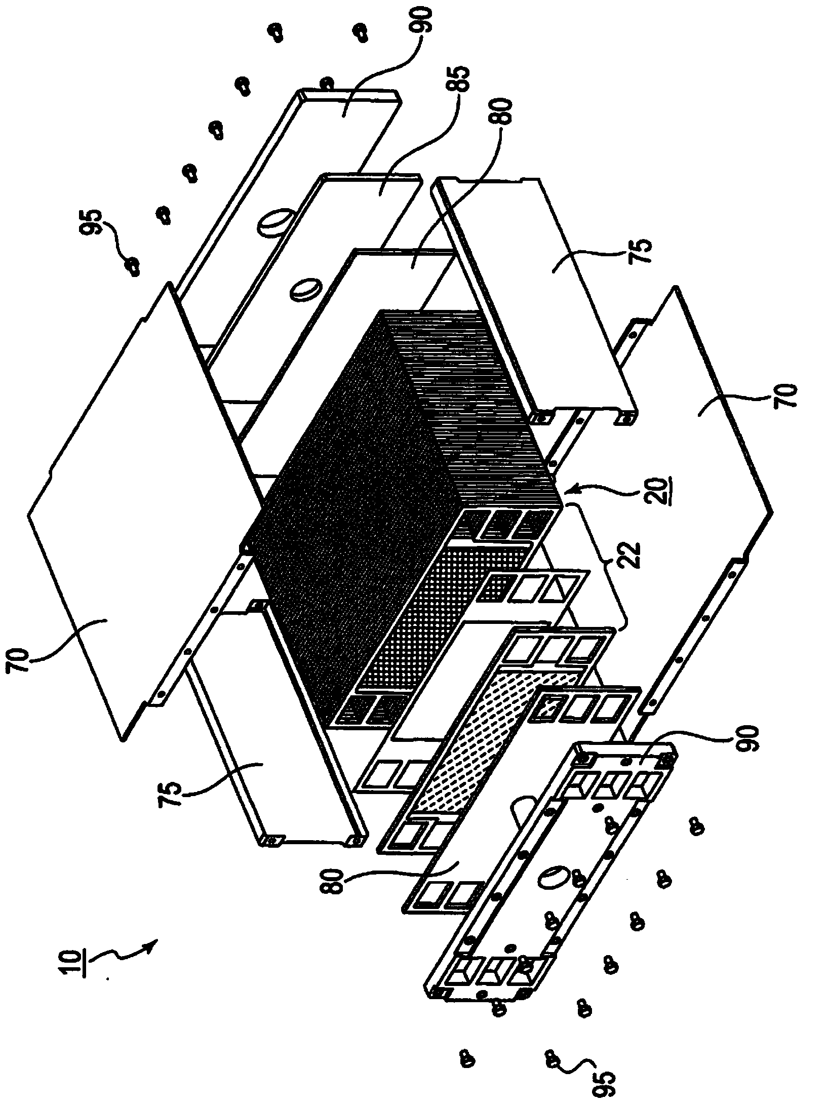
[0036] figure 1 is an exploded perspective view for describing the fuel cell according to the first embodiment.
[0037] The fuel cell 10 according to the first embodiment is easy to miniaturize, has good gas diffusibility, and can uniformly distribute its surface pressure. For example, it is formed from a polymer electrolyte fuel cell using hydrogen gas as a fuel, and is used as a power source. With polymer electrolyte fuel cells (PEFCs), miniaturization, higher density, and increased power are possible. It is preferably used as a power source for driving a movable object having a limited installation space such as a vehicle, and is particularly preferably applied to an automobile whose system starts and stops frequently or whose output changes frequently. In this case, for example, the PEFC can be installed under the seat in the center portion of the vehicle body of the automobile (fuel cell automobile), in the lower portion of the rear trunk room, and in the engine room ...
no. 2 approach
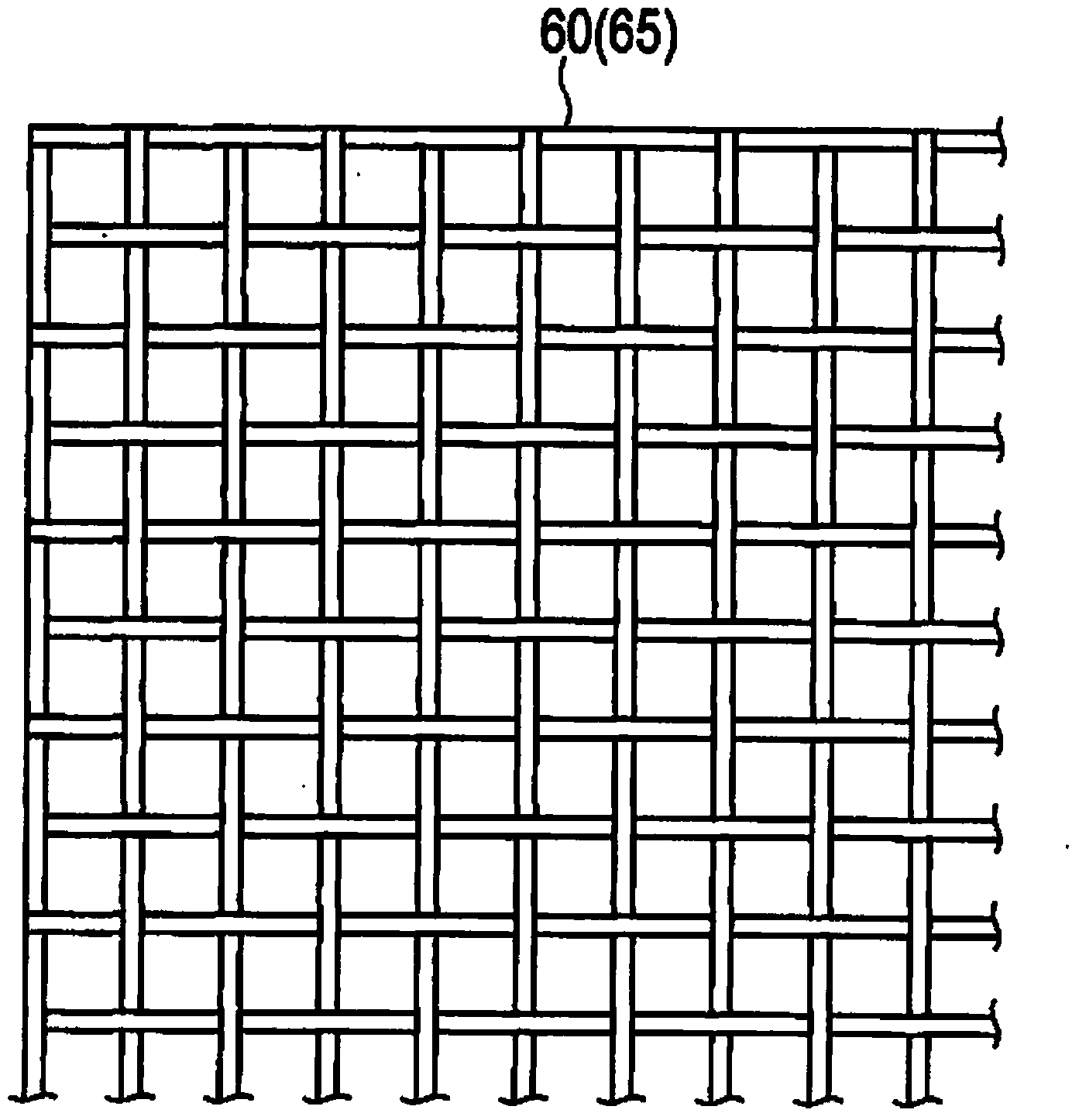
[0088] Figure 4 is a sectional view for describing the fuel cell according to the second embodiment, Figure 5 is used to describe Figure 4 A plan view of the rib is shown in .
[0089] The fuel cell according to the second embodiment is roughly different from the fuel cell according to the first embodiment in that the fuel cell according to the second embodiment has ribs 50A and 55A as separate bodies that are not integrally formed with separators 40 and 45 . Hereinafter, components having the same functions as those in the first embodiment are denoted by the same reference numerals, and descriptions of such components are omitted to avoid repetition.
[0090] The ribs 50A and 55A are made of a wire material having a circular cross section, and are fixed to the supports 60 and 65 . Therefore, even if the shapes of the ribs 50A and 55A are not linear, since the contact points between the ribs 50A and 55A and the supports 60 and 65 are fixed, the bending of the supports 6...
no. 3 approach
[0099] Figure 6 is a sectional view for describing the fuel cell according to the third embodiment.
[0100] The fuel cell according to the third embodiment is roughly different from the fuel cell according to the first embodiment in that the fuel cell according to the third embodiment has a single support body 65A.
[0101] The support body 65A has a bending rigidity smaller than that of the membrane electrode assembly 30 , and is disposed on the cathode side of the membrane electrode assembly 30 , and between the catalyst layer 36 and the separator 45 .
[0102] The reason why the bending rigidity of the support body 65A is smaller than that of the membrane electrode assembly 30 is that the support body 65A does not exist on the anode side of the membrane electrode assembly 30 and the small bending rigidity results in uniform surface pressure. The reason why the support body 65A is arranged on the cathode side is that the effect of gas diffusivity is greater on the cathode...
PUM
| Property | Measurement | Unit |
|---|---|---|
| width | aaaaa | aaaaa |
| diameter | aaaaa | aaaaa |
| particle size | aaaaa | aaaaa |
Abstract
Description
Claims
Application Information