Bead rotating plate of beading machine
A beading machine and turntable technology, which is applied in the decoration of textiles, textiles and papermaking, etc., can solve the problems that the transmission speed cannot keep up with the transmission speed of buttons, reduce the efficiency of beading, and beading defective products, etc., so as to speed up the transmission Speed, improve beading efficiency, fast transmission effect
- Summary
- Abstract
- Description
- Claims
- Application Information
AI Technical Summary
Problems solved by technology
Method used
Image
Examples
Embodiment 1
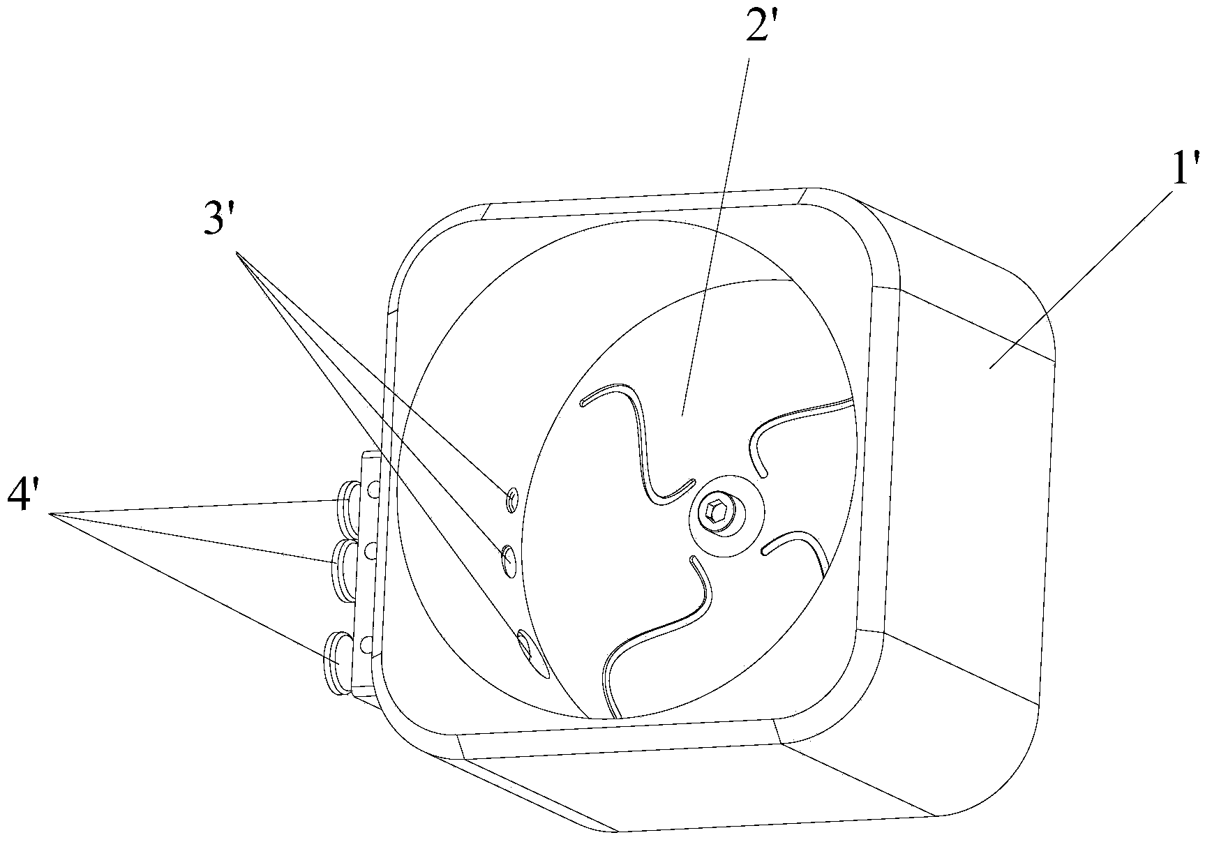
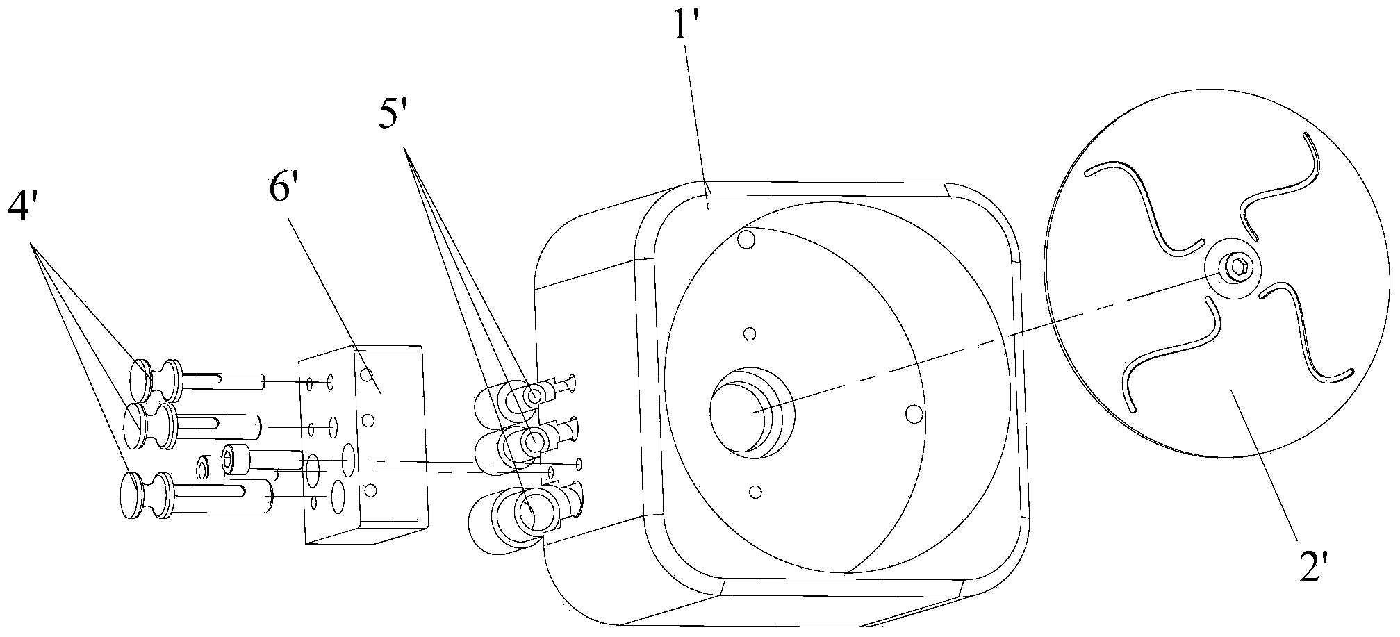
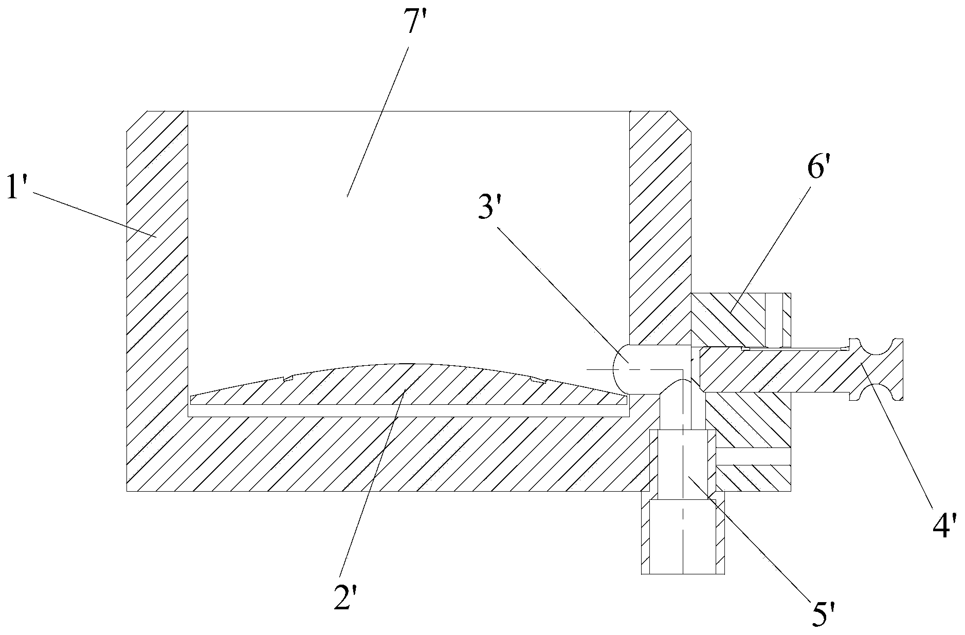
[0040] See Figure 5-Figure 10 , Figure 5 It is the overall structural diagram of the bead turntable of the bead nailing machine in Embodiment 1 of the present invention; Figure 6 It is an exploded view of the main components in the bead turntable of the bead nailing machine in Example 1 of the present invention; Figure 7 It is an overall structural diagram of another angle of the bead turntable of the bead nailing machine in Embodiment 1 of the present invention; Figure 8 for Figure 7 A-A sectional view of the bead turntable of the bead nailing machine; Figure 9 for Figure 8 The partial enlarged view of part B in the figure, the magnification ratio in the figure is 20:1. Figure 10 It is a cross-sectional view of the structure of the bead ejector in the bead turntable of the bead nailing machine in Embodiment 1 of the present invention.
[0041] The bead turntable of the bead nailing machine provided by the embodiment of the present invention includes a turntable...
Embodiment 2
[0053] The bead turntable of the bead nailing machine provided by the embodiment of the present invention includes a turntable main body, a rotating paddle and a bead ejector, wherein: the turntable main body is provided with a groove for containing beads; the rotating paddle is installed in the groove of the turntable main body; A fixing hole is arranged at the bottom of the groove, and the bead outlet piece is sleeved in the fixing hole, and the bead outlet piece is provided with a bead outlet hole.
[0054] The beads are placed in the groove containing the beads, and the rotating paddle is driven by the motor to rotate to drive and stir the beads. The rotating paddle drives the beads to move in the groove. The diameter of the bead hole is slightly larger than the diameter of the bead. When going out of the bead hole of the piece, the beads fall from the bead hole due to the effect of gravity. Because the beads are constantly moving under the action of the stirring paddle, t...
Embodiment 3
[0066] The bead turntable of the bead nailing machine provided by the embodiment of the present invention includes a turntable main body, a rotating paddle and a bead ejector, wherein: the turntable main body is provided with a groove for containing beads; the rotating paddle is installed in the groove of the turntable main body; A fixing hole is arranged at the bottom of the groove, and the bead outlet piece is sleeved in the fixing hole, and the bead outlet piece is provided with a bead outlet hole.
[0067]The beads are placed in the groove containing the beads, and the rotating paddle is driven by the motor to rotate to drive and stir the beads. The rotating paddle drives the beads to move in the groove. The diameter of the bead hole is slightly larger than the diameter of the bead. When going out of the bead hole of the piece, the beads fall from the bead hole due to the effect of gravity. Because the beads are constantly moving under the action of the stirring paddle, th...
PUM
 Abstract
Description
Claims
Application Information
 - R&D
- Intellectual Property
- Life Sciences
- Materials
- Tech Scout
- Unparalleled Data Quality
- Higher Quality Content
- 60% Fewer Hallucinations
Browse by: Latest US Patents, China's latest patents, Technical Efficacy Thesaurus, Application Domain, Technology Topic, Popular Technical Reports.
© 2025 PatSnap. All rights reserved.Legal|Privacy policy|Modern Slavery Act Transparency Statement|Sitemap|About US| Contact US: help@patsnap.com


