Supercharge Your Innovation With Domain-Expert AI Agents!

Device for anchoring a belt lock

A belt lock and anchoring technology, applied in belt fixing devices, applications, seat belts in cars, etc., can solve the problems that cannot be implemented, cannot be easily realized, and the sewing process is difficult

Active Publication Date: 2014-12-03
TRW AUTOMOTIVE GMBH
View PDF7 Cites 2 Cited by
  • Summary
  • Abstract
  • Description
  • Claims
  • Application Information

AI Technical Summary

Problems solved by technology

But such a setting cannot be realized easily, because the sewing process for forming the loop is very difficult or impossible to carry out in the case of very short safety belts

Method used


Image

  • Device for anchoring a belt lock
  • Device for anchoring a belt lock

Examples


Embodiment Construction

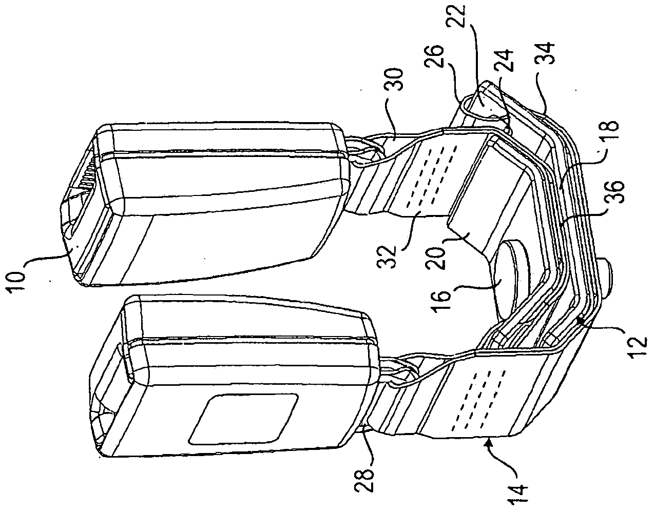
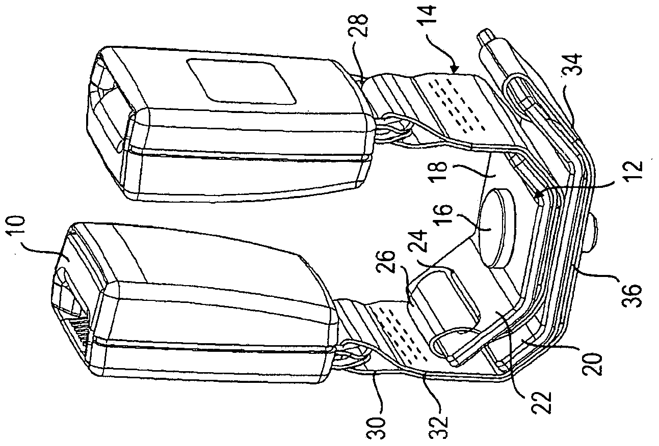
[0020] exist figure 1 and 2 shows a combination of two anchoring devices, by means of which two belt locks 10 can be anchored to a vehicle. Both devices are constructed substantially identically and have substantially the same dimensions. Each device comprises, as essential components, a fitting 12 and an attachment strap 14 in the form of a safety belt, such as a seat belt. Fastening of the fittings 12 of the two devices is achieved by means of a common screw 16 .

[0021] Each fitting 12 is designed as a single layer and starts from a flat middle section 18—with reference to the assembled state of the device—with an upwardly bent first end section 20 and an opposite, likewise upwardly bent A curved second end section 22 that is slightly longer than the first end section 20 . A hole is formed in the middle section 18 for a screw 16 which defines the anchor point of the device. A fitting grommet 24 is formed in the second end section 22 .

[0022] The connecting strip 14...


PUM


Abstract

The invention relates to a device for anchoring a belt lock (10), comprising a fitting (12) which has a first end section (20) and a second end section (22) as well as a middle section (18) located between the two end sections (20, 22). The middle section (18) has an opening for securing the fitting (12) fixedly to the vehicle by means of a screw (16). The device further comprises a connecting strip (14) that is connected to both the belt lock (10) and the fitting (12). According to the invention, the connecting strip (14) runs along the first end section (20) and along the middle section (18) of the fitting (12) and is threaded via a loop (30) into an eyelet (24) in the second end section (22).

Description

technical field [0001] The invention relates to a device for anchoring a belt lock according to the preamble of claim 1 . The invention also relates to a device system comprising at least two such devices. Background technique [0002] In order to be able to achieve high flexibility of the connection, belt anchors are used, in which the belt lock is fastened to the anchor point via a flexible connecting strap (usually a safety strap). The safety belt is usually fastened via a first loop to the belt buckle and via a second loop to a fastening shackle fastened to the vehicle. The length of the connecting strap between the two loops is predetermined at the maximum distance between the anchor point of the strap lock and the position of use. This distance should be as short as possible for the intended application. However, such an arrangement cannot be realized easily, because the sewing process for forming the loop is very difficult or not possible at all in the case of very...

Claims


Application Information

Patent Timeline
Patent Type & Authority Applications(China)
IPC IPC(8): B60R22/22B60R22/18
CPCB60R2022/1806B60R22/22Y10T24/318B60R22/18
Inventor P·哈斯D·施密德
Owner TRW AUTOMOTIVE GMBH
Features
  • R&D
  • Intellectual Property
  • Life Sciences
  • Materials
  • Tech Scout
  • Unparalleled Data Quality
  • Higher Quality Content
  • 60% Fewer Hallucinations
Learn More