
Wheelbarrow with auxiliary wheel

A technology for auxiliary wheels and unicycles, applied to bicycles, motorcycles, motor vehicles, etc., can solve problems such as bruises, calf and side wall discomfort, etc., to increase comfort and solve the effect of inconvenient riding

Active Publication Date: 2014-12-10
浙江西塘实业有限公司
View PDF4 Cites 14 Cited by
  • Summary
  • Abstract
  • Description
  • Claims
  • Application Information

AI Technical Summary

Problems solved by technology

The rise of self-balancing electric unicycles is about to trigger a new traffic revolution; when riding an existing electric unicycle, it is necessary to step on the pedal with one foot first, and the calf and the side wall are offset to form a stable triangular structure. Then stand on the other leg to realize the riding action; but the calf and the side wall are very uncomfortable, and it will cause bruises after riding for a long time

Method used


Image

  • Wheelbarrow with auxiliary wheel
  • Wheelbarrow with auxiliary wheel
  • Wheelbarrow with auxiliary wheel

Examples


Embodiment 1

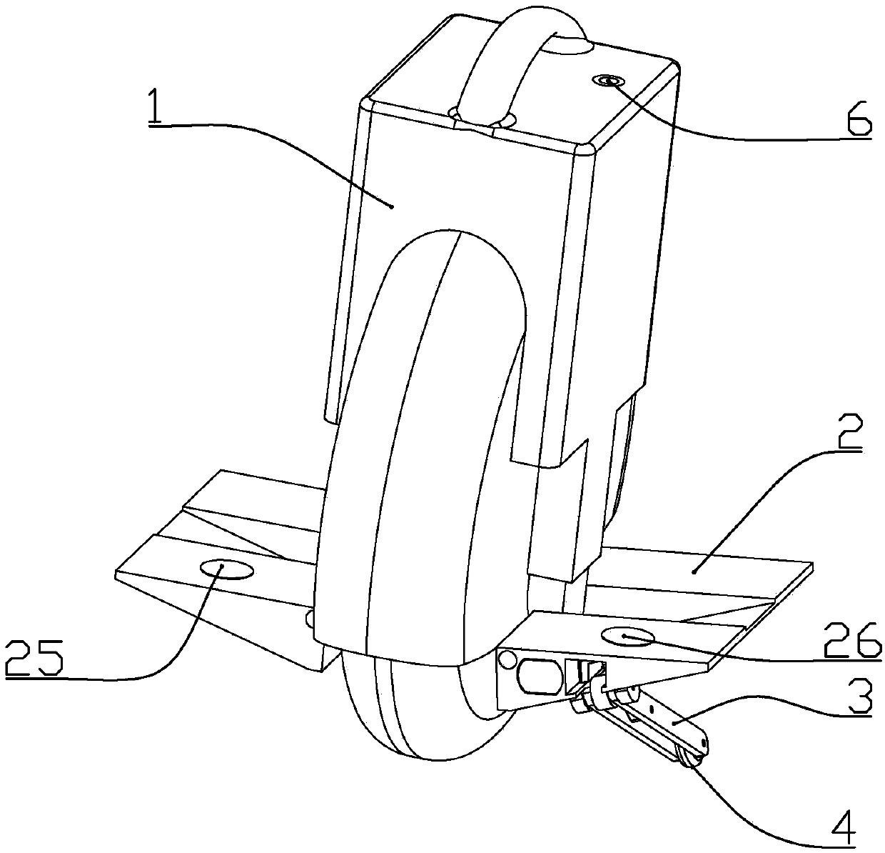
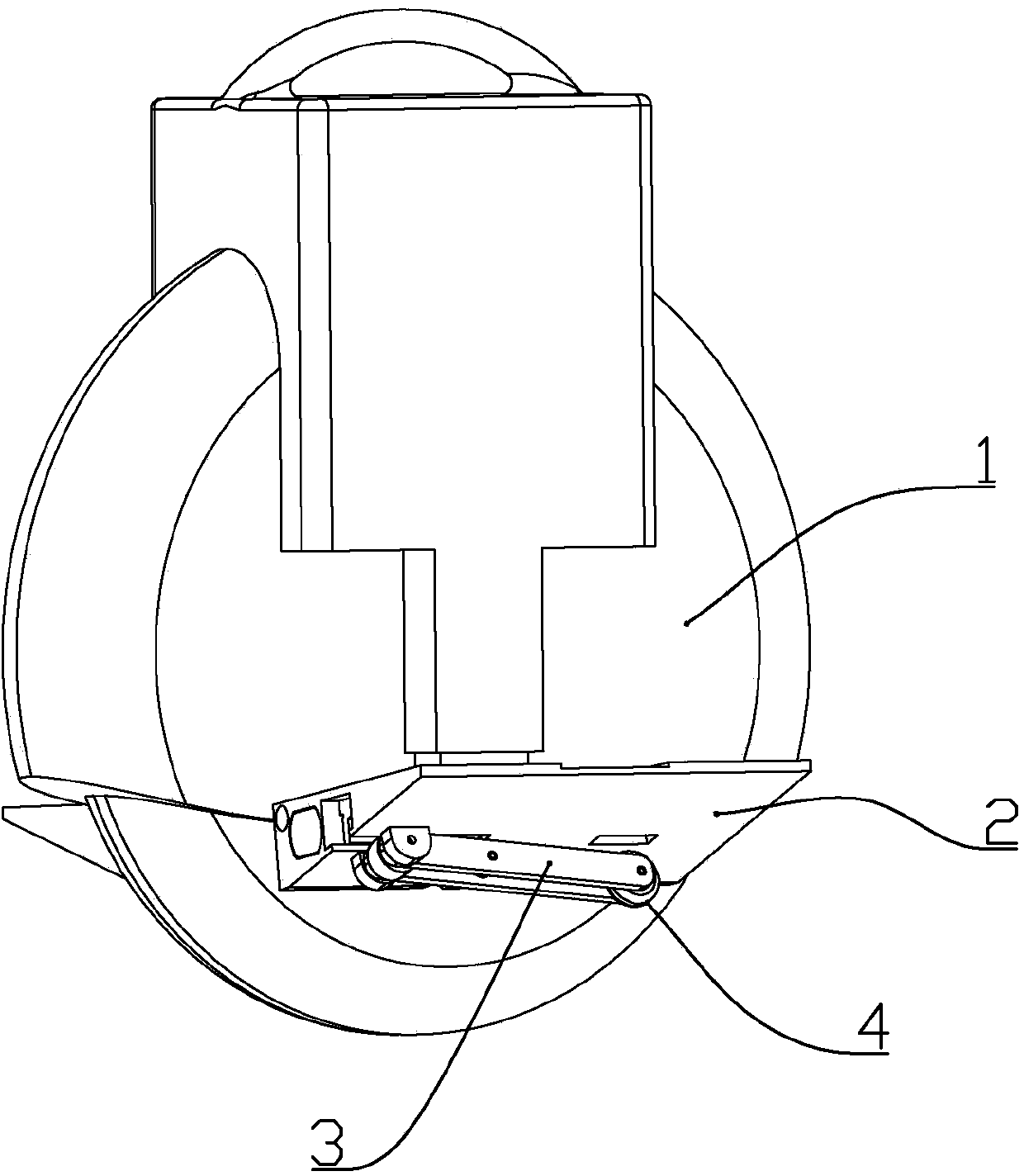
[0016] according to figure 1 As shown, a unicycle with auxiliary wheels described in this embodiment includes a vehicle body 1, and a pedal 2 is respectively arranged on both sides of the vehicle body, and the pedal is hinged with the vehicle body through a connecting shaft. The upper part of the vehicle body is provided with a power switch 6, the lower surface of one of the pedals is equipped with an auxiliary wheel system with liftable auxiliary wheels, the upper surface is equipped with a switch B26 for controlling the lowering of the auxiliary wheels, and the upper surface of the other pedal is installed with a control wheel. Switch A25 for training wheels stowed.

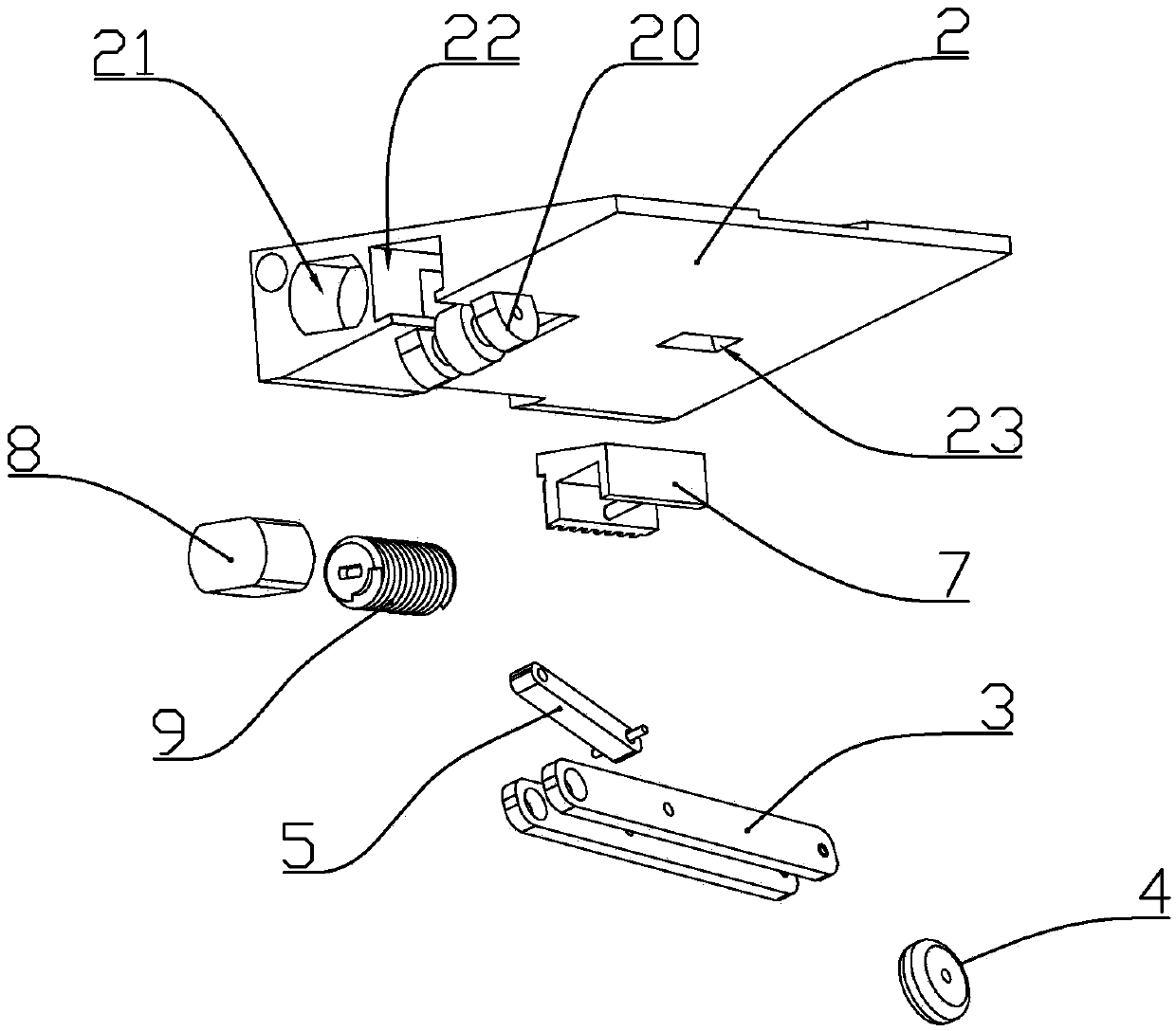
[0017] The auxiliary wheel system includes the auxiliary wheel 4, the support rod 3 for installing the auxiliary wheel, the mounting seat 20 formed under the pedal and rotatably connected with the support rod, and the support rod rotatably connected with the middle part of the support rod. Drive rod 5, and a s...

Embodiment 2

[0025] A unicycle with auxiliary wheels described in this embodiment includes a body, a pedal is arranged on each side of the body, the pedal is hinged to the body through a connecting shaft, and the upper part of the body is provided with a power supply The switch is characterized in that: an auxiliary wheel system with liftable auxiliary wheels is installed on the lower surface of one pedal, a switch B for controlling the lowering of the auxiliary wheels is installed on the upper surface, and a control auxiliary wheel system is installed on the upper surface of the other pedal. The retracted switch A; the auxiliary wheel system includes the auxiliary wheel, the support rod for installing the auxiliary wheel, the mounting seat formed under the pedal and connected to the support rod in rotation, and the middle part of the support rod A drive rod connected in rotation, and a slider connected in rotation with the other end of the drive rod, a slide rail for the slide block to sli...


PUM


Abstract

The invention discloses a wheelbarrow with an auxiliary wheel. The wheelbarrow comprises a wheelbarrow body, pedals and a power supply switch, wherein an auxiliary wheel system with a liftable auxiliary wheel is mounted on the lower surface of one of the pedals, and a switch B for controlling the auxiliary wheel to descend is mounted on the upper surface of the pedal; a switch A for controlling the auxiliary wheel to withdraw is mounted on the upper surface of the other pedal; the auxiliary wheel system comprises the auxiliary wheel, a supporting rod for mounting the auxiliary wheel, a mounting base formed below the pedal and rotationally connected with the supporting rod, a driving rod rotationally connected with the middle part of the supporting rod, and a sliding block rotationally connected with the other end of the driving rod; a driving system for driving the sliding block to slide is further mounted in one of the pedals; the driving system comprises a motor mounted in the pedal, and a lead screw; a gear rack matched with and connected with the lead screw in a transmission manner is formed on the side surface of the sliding block; a motor mounting cavity, a lead screw mounting cavity and a sliding rail are arranged at the end part of one of the pedals.

Description

technical field [0001] The invention belongs to the field of unicycle structure, and in particular relates to a unicycle with auxiliary wheels. Background technique [0002] Self-balancing electric unicycle is a means of transportation with electric drive and self-balancing function. With the rapid development of society today, traffic congestion has become a common phenomenon. Electric unicycles replace bicycles and electric vehicles as transportation tools. The rise of self-balancing electric unicycles is about to trigger a new traffic revolution; when riding an existing electric unicycle, it is necessary to step on the pedal with one foot first, and the calf and the side wall are offset to form a stable triangular structure. Then stand on the other leg to realize the riding action; but the calf and the side wall are very uncomfortable, and it will cause bruises after riding for a long time. Contents of the invention [0003] The technical problem to be solved by the p...

Claims


Application Information

Patent Timeline
IPC IPC(8): B62H1/12B62K11/00
Inventor 李陈
Owner 浙江西塘实业有限公司
Learn More