Eureka AIR delivers breakthrough ideas for toughest innovation challenges, trusted by R&D personnel around the world.

Rod pump pressure relieving tool

A technology for rod pumps and tools, which is applied in variable capacity pump parts, pump elements, components of pumping devices for elastic fluids, etc., and can solve the problem of small fitting clearance of rod pumps and increased frequency of rod pump jams , lack of pressure relief tools, etc., to avoid repeated pump inspections and eliminate operational risks

Active Publication Date: 2014-12-10
SOUTHWEST PETROLEUM UNIV +1
View PDF4 Cites 0 Cited by
  • Summary
  • Abstract
  • Description
  • Claims
  • Application Information

AI Technical Summary

Problems solved by technology

[0002] With the deepening of my country's oilfield development process, the formation energy gradually decays, the fluid supply capacity of oil wells deteriorates, and the dynamic fluid level of mechanically pumped wells decreases year by year. The large-scale application of rod pump deep pumping technology has achieved remarkable results. There are some disadvantages: the rod pump has a small fit gap, and it is prone to pump stuck faults. With the continuous promotion of gas injection technology, the frequency of rod pump stuck pumps has further increased due to the influence of gas injection well scaling and corrosion.
[0003] In order to find out why the pump is stuck, the rod pump must be disassembled, and the gas injection will easily cause the pressure in the pump barrel of the rod pump to be suppressed. Professional pressure relief tools assist in dismantling the pump safely, which can easily lead to personal injury accidents

Method used


Image

  • Rod pump pressure relieving tool
  • Rod pump pressure relieving tool

Examples


Embodiment Construction

[0013] In the following, the present invention will be specifically described through exemplary embodiments. It should be understood, however, that elements, structures and characteristics of one embodiment may be beneficially incorporated in other embodiments without further recitation.

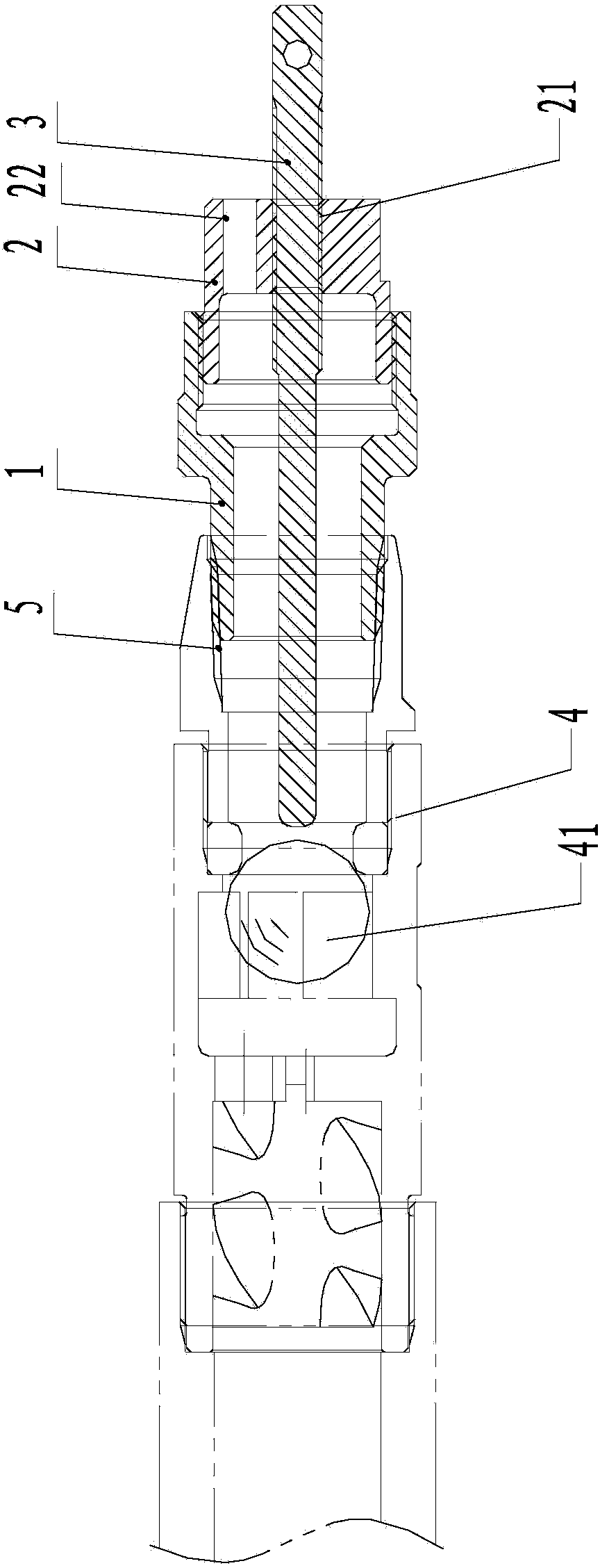
[0014] see figure 1 , is a structural schematic diagram of the first embodiment of the rod pump pressure relief tool in the present invention. As shown in the figure, the rod pump pressure relief tool in the present invention includes a sleeve 1 that matches the rod pump, and the sleeve 1 There is a rotatable ejector rod 3 inside, and the ejector rod 3 is facing the valve ball 41 inside the rod pump 4 pump cylinder. The high-pressure gas or high-pressure liquid in the leak out. In the first embodiment of the present invention, the sleeve 1 is sheathed on the bottom of the rod pump 4, and two sets of mounting holes are provided on the sleeve 1, wherein one set of mounting holes 11 is in lin...


PUM


Abstract

The invention provides a rod pump pressure relieving tool which comprises a sleeve matched with a rod pump, and an ejector rod which can rotate is arranged in the sleeve. The ejector rod is right opposite to a valve ball in a cylinder of the rod pump. When the rod pump pressure relieving tool is used, the ejector rod is rotated until the ejector rod ejects the valve ball away so that the high-pressure gas or high-pressure liquid in the rod pump can be discharged. According to the rod pump pressure relieving tool, due to the fact that the ejector rod capable of ejecting the valve ball in the rod pump away is arranged, simple, safe and fast pressure relieving can be achieved.

Description

technical field [0001] The invention relates to a pressure relief tool, in particular to a pressure relief tool for a rod pump. Background technique [0002] With the deepening of my country's oilfield development process, the formation energy gradually decays, the fluid supply capacity of oil wells deteriorates, and the dynamic fluid level of mechanically pumped wells decreases year by year. The large-scale application of rod pump deep pumping technology has achieved remarkable results. There are some disadvantages: the rod pump has a small fit clearance, and it is prone to pump stuck faults. With the continuous promotion of gas injection technology, the frequency of rod pump stuck pumps has further increased due to scaling and corrosion of gas injection wells. [0003] In order to find out why the pump is stuck, the rod pump must be disassembled, and the gas injection will easily cause the pressure in the pump barrel of the rod pump to be suppressed. Professional pressure ...

Claims


Application Information

Patent Timeline
Patent Type & Authority Applications(China)
IPC IPC(8): F04B53/22
Inventor 程晓军董斌任爱军杨兆中刘毅曾涛施硕杨小辉徐鑫于国龙
Owner SOUTHWEST PETROLEUM UNIV
Why Eureka
Eureka Blog
Learn More