Sequence-program debugging assistance apparatus

A technology of sequencing programs and auxiliary devices, applied in program control, electrical program control, program control in sequence/logic controllers, etc., can solve problems such as non-execution of programs, and achieve the effect of reducing man-hours

Inactive Publication Date: 2014-12-10
MITSUBISHI ELECTRIC CORP
View PDF8 Cites 10 Cited by
  • Summary
  • Abstract
  • Description
  • Claims
  • Application Information

AI Technical Summary

Problems solved by technology

(3) Failure to execute t

Method used


Image

  • Sequence-program debugging assistance apparatus
  • Sequence-program debugging assistance apparatus
  • Sequence-program debugging assistance apparatus

Examples


Embodiment approach 1

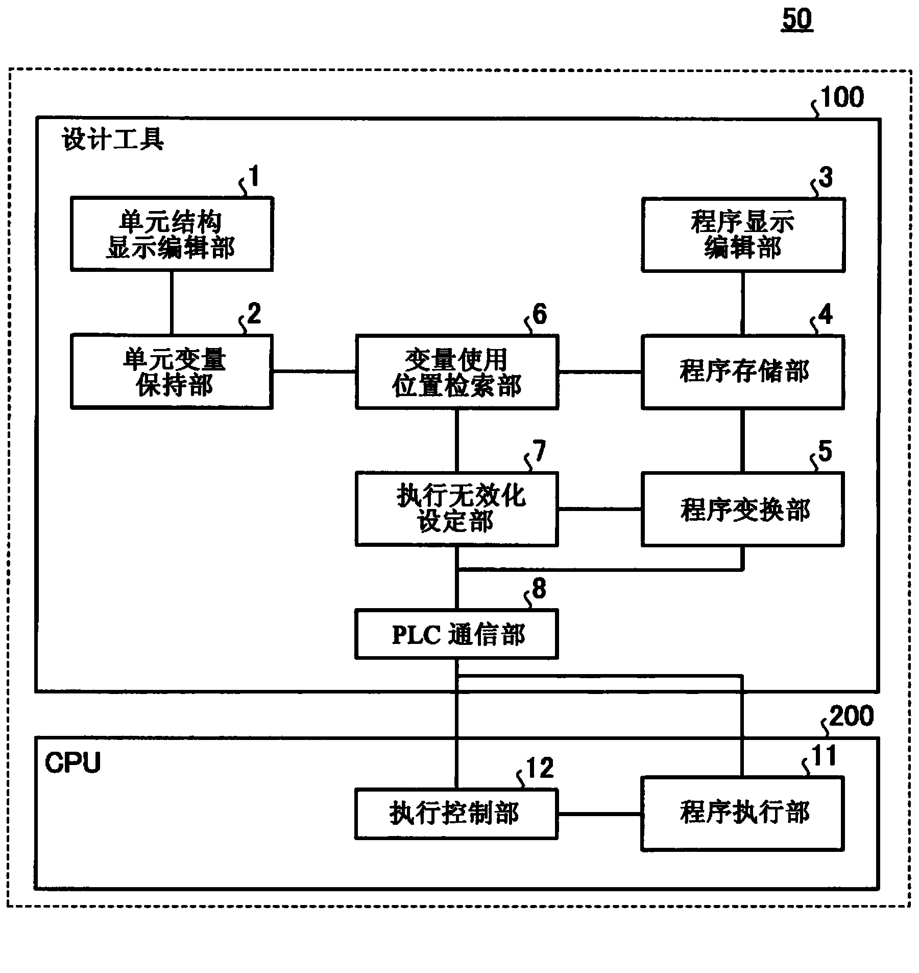
[0029] exist figure 2 The basic configuration of the sequence program debugging support device 50 according to Embodiment 1 of the present invention is shown in . As a basic structure for realizing the sequence program debugging support device 50, it is conceivable to have a computer or the like on which design tool software is installed, that is, a design tool 100, and a CPU 200 (hardware) of a programmable logic controller (PLC) that executes a program created by the design tool 100. ) structure. The CPU 200 is a part of a programmable logic controller (PLC) main body (not shown as a whole).

[0030] The outline of each constituent element will be described below. The design tool 100 is a tool for editing a program operating in the PLC system, and is realized by, for example, a computer on which design tool software is installed. The design tool 100 has each processing unit shown below.

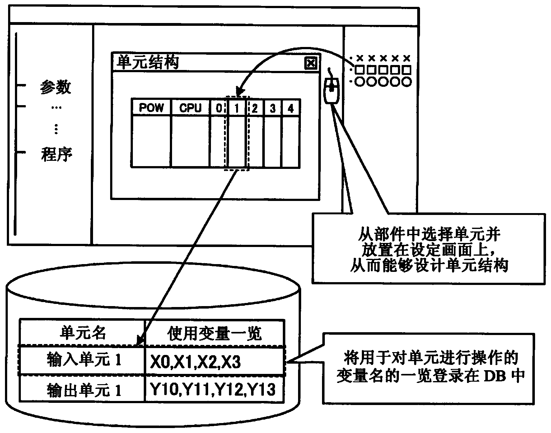
[0031] Cell Structure Display Editorial 1:

[0032] It is an editor that can set ...

Embodiment approach 2

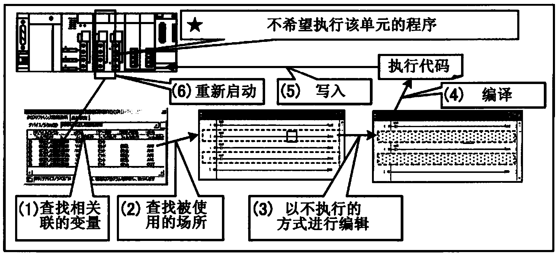
[0088] In addition, in Embodiment 1, it is assumed that the user manually selects the unit to be invalidated on the unit configuration diagram in the (execution invalidation operation of the program using the unit), but in the actual system of the PLC, there are In the case of the unit, this operation can also be omitted.

[0089] In this embodiment, if Figure 13 As shown, the sequence program debugging support device 50 includes an automatic recognition unit 20 having a function of automatically recognizing a unit not mounted on a programmable logic controller (PLC) (unconnected unit). Such as Figure 13 As shown, the automatic recognition unit 20 may be provided only on the CPU 200 (hardware) side to notify the design tool 100 (software) of the recognition result, or it may be shared by the CPU 200 and the design tool 100 . exist Figure 14 The operation flow of this embodiment including the operation of the sequence program debugging support device 50 is shown in .

[...


PUM


Abstract

A sequence-program debugging assistance apparatus (50) according to an embodiment includes an engineering tool (100) and an execution control section (12). The engineering tool (100) includes a configuration editing section (1) that receives information indicating a unit to be disabled selected from a programmable logic controller by a user, a variable holding section (2) that holds variables to be used by units in a sequence program, a program editing section (3) that can edit the sequence program, a storage section (4) that stores the sequence program, a conversion section (5) that converts the sequence program to execution code executable by an executing section (11), a search section (6) that acquires a variable to be used by the unit to be disabled from the variable holding section and searches the sequence program for a location where the acquired variable is used, and a disabling setting section (7) that writes a region corresponding to the location in the execution code into a disabled-region setting file as a disabled region where execution is disabled. The execution control section (12) controls, on the basis of the disabled-region setting file, the executing section so as not to execute the disabled region.

Description

technical field [0001] The invention relates to an auxiliary device for debugging a sequence program. Background technique [0002] When checking the operation of a programmable logic controller (PLC) system during a sequence program debugging operation, etc., when it is not desired to execute the operation program related to a specific unit in the system, in the existing design tool, A series of operations as described below are required. [0003] (1) For the target unit, search the list of variables used in the program. (2) Specify the location (plurality) of the program using the retrieved variable. (3) The determined program is not executed. Specifically, editing operations such as backing up and deleting the program and commenting out are performed. (4) Compile the program (generate execution code). (5) Write the compiled execution code into a programmable logic controller (PLC). (6) Restart the programmable logic controller (PLC). [0004] For example, Patent Do...

Claims


Application Information

Patent Timeline
IPC IPC(8): G05B19/05
CPCG05B19/05G05B19/056G05B2219/13142G06F11/3636G06F11/3624
Inventor 山冈孝行
Owner MITSUBISHI ELECTRIC CORP
Why Eureka
Try Eureka