Eddy current reducer

A deceleration device and eddy current technology, applied in the direction of electromechanical devices, electrical components, electric components, etc., can solve the problems of insufficient cylinder force, inability to seek low cost and miniaturization, and achieve the effect of reducing the force required for work

Active Publication Date: 2017-06-16
NIPPON STEEL CORP
View PDF8 Cites 0 Cited by
  • Summary
  • Abstract
  • Description
  • Claims
  • Application Information

AI Technical Summary

Problems solved by technology

However, in order to further reduce the cost and size of the entire device, in the speed reducer proposed in Patent Document 4, the power of the air cylinder is insufficient.
On the other hand, if a cylinder that satisfies the specified push-pull force is used, it will not be possible to achieve low cost and miniaturization

Method used


Image

  • Eddy current reducer
  • Eddy current reducer
  • Eddy current reducer

Examples


Embodiment

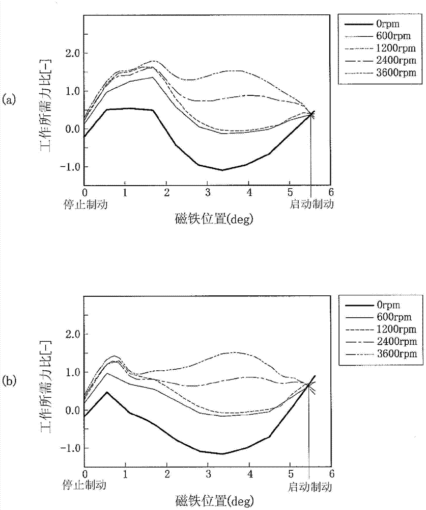
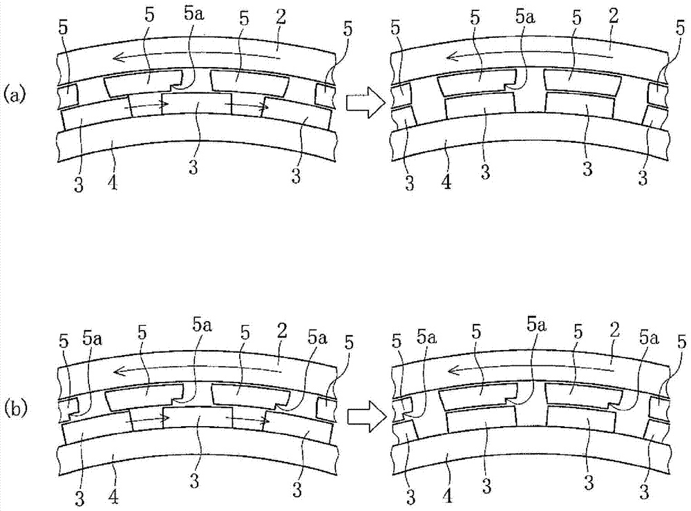
[0048] Figure 12 is used Figure 13 It is a diagram of the moving direction of the magnet supporting member 4 in the conventional speed reducer of the single-row rotation method of the pole piece 5 having the shape shown. in addition, Figure 14 It means that the numerical analysis obtained in Figure 10 A graph showing the results of the required operating force when switching between start braking and stop braking when the technology proposed by the applicant in Patent Document 4 is applied to the conventional speed reducer of the single-row rotary system shown. .

[0049] Figure 14 is the patent document 4 and Figure 6 Equivalent figure, patent document 4 can be obtained with Figure 6 The same result is obtained for the single-row rotary speed reducer shown by the solid line. In this way, it can be confirmed that in the technology proposed in Patent Document 4, when switching from stop braking to start braking, the diamagnetic field accompanied by the eddy current...


PUM


Abstract

In the eddy current type speed reducer of the single-row rotary system, the device is further reduced in size without increasing the number of components, and at the same time, the cost is reduced and the operation force required for switching between start braking and stop braking is reduced. The magnet supporting member (4) of the ferromagnetic body is arranged in a manner opposite to the brake drum (2) and capable of rotating and moving at a required angle. The magnet supporting member (4) of the ferromagnetic body is installed so that the orientation of the magnetic pole is along the The circumferential direction of the brake drum (2) of the shaft (1) is formed so that permanent magnets (3) are alternately arranged at constant intervals in opposite directions. The supporting body (3) is arranged between the permanent magnet group and the brake drum (2), and the supporting body (3) makes the non-magnetic supporting member (6a) which has been arranged between the pole pieces (5) be interposed The ferromagnetic body arranged at substantially the same angular position as the permanent magnet (3) is arranged between the pole piece (5) group of the ferromagnetic body arranged at substantially the same angular position as the permanent magnet (3). The pole shoe (5) group. A notch ( 5a).

Description

technical field [0001] The present invention relates to an eddy current type deceleration device (hereinafter referred to as a decelerator) for a vehicle mounted as an auxiliary brake on, for example, a large or medium-sized bus or truck. In particular, an eddy current type speed reducer is intended to reduce the operating force (hereinafter, referred to as the required operating force) required for switching between start braking and stop braking. Background technique [0002] For example, in the case of a large vehicle such as a truck or a bus, in addition to a service brake (friction brake) as a main brake, an engine brake and an exhaust brake are mounted as auxiliary brakes. In recent years, the performance of engine brakes and exhaust brakes has been reduced due to the downsizing of engines mounted on vehicles, and thus the introduction of speed reducers to enhance auxiliary brakes has become more common. [0003] The speed reducer is roughly divided into a method usin...

Claims


Application Information

Patent Timeline
Patent Type & Authority Patents(China)
IPC IPC(8): H02K49/02H02K49/10
CPCH02K49/043H02K49/046
Inventor 今西宪治斋藤晃野上裕野口泰隆山口博行奥田洋三
Owner NIPPON STEEL CORP
Why Eureka
Try Eureka