
Stirring device with detachable shaft sleeve

A stirring device and detachable technology, which is applied in the field of detachable shaft sleeve stirring devices, can solve the problems of shaft sleeve wear, the bottom cannot be disassembled, and the replacement of the shaft sleeve is cumbersome, etc., so as to ensure stability, improve service life, and reduce friction. Effect

Inactive Publication Date: 2014-12-17
诸城兴贸玉米开发有限公司
View PDF0 Cites 3 Cited by
  • Summary
  • Abstract
  • Description
  • Claims
  • Application Information

AI Technical Summary

Problems solved by technology

[0002] Stirring equipment is commonly used in starch, food and other industries. In order to increase the stability of the stirring shaft, a shaft sleeve is usually installed at the bottom of the mixing tank to fix the stirring shaft. Wear and tear will occur after a while. Due to the integrated design of the mixing cylinder of the current mixing equipment, the bottom cannot be disassembled. If the shaft sleeve is replaced, it needs to be disassembled from the top of the mixing equipment, which makes the replacement of the shaft sleeve cumbersome and is not conducive to saving time. and labor costs

Method used


Image

  • Stirring device with detachable shaft sleeve
  • Stirring device with detachable shaft sleeve

Examples


Embodiment Construction

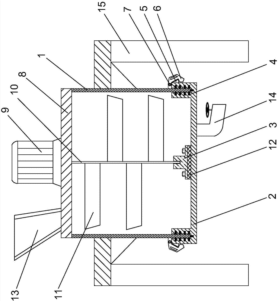
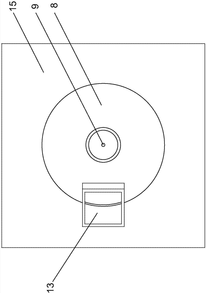
[0011] Such as figure 1 , 2 As shown, the shaft sleeve detachable mixing device of the present invention comprises a mixing tank 1, a base 2, and a shaft sleeve 3. Correspondingly, a plurality of sealing rings 4 are arranged in the groove, and a plurality of blocks 5 are arranged on the outside of the base 2, and the blocks 5 correspond to the fixed handle 6 provided on the outside of the bottom of the mixing bucket 1, and the fixed handle 6 passes through the rotating shaft 7 is connected to the outer wall of the mixing bucket 1, the base 2 is fixed in the bottom of the mixing bucket 1 through the clamping block 5 in the fixed handle 6, the mixing bucket cover 8 is arranged above the mixing bucket 1, and the motor 9 is arranged above the mixing bucket cover 8 , the inside of the mixing tank 1 is provided with a stirring shaft 10 driven by a motor 9, and stirring blades 11 are evenly arranged on the stirring shaft 10, and the bushing 3 is installed on the base 2 inside the mi...


PUM


Abstract

The invention discloses a stirring device with a detachable shaft sleeve. The stirring device comprises a stirring tank, a base and the shaft sleeve. Both the upper end and the lower end of the stirring tank are open. The base is provided with a circle of grooves corresponding to the bottom of the stirring tank, and a plurality of seal rings are arranged in the grooves. A plurality of clamp blocks are arranged on the outer side of the base and are corresponding to fixed handles arranged on the outer side of the bottom of the stirring tank, the fixed handles are connected with the outside wall of the stirring tank through a rotating shaft, and the base is fixed at the bottom of the stirring tank by being fixed in the fixed handles through the clamp blocks. The shaft sleeve is arranged on the base disposed in the stirring tank through a bolt, the bottom of a stirring shaft is located in the shaft sleeve, and a shock pad is arranged between the shaft sleeve and the base. The base disposed at the bottom of the stirring tank can be detached so that the shaft sleeve can be replaced conveniently and timely, and shaft sleeve replacement time and labor cost are saved. In addition, materials remained in the stirring tank can be cleaned thoroughly to be discharged thoroughly, and the weight of follow-up materials can be ensured.

Description

technical field [0001] The invention relates to a stirring device, in particular to a detachable shaft sleeve stirring device. Background technique [0002] Stirring equipment is commonly used in starch, food and other industries. In order to increase the stability of the stirring shaft, a shaft sleeve is usually installed at the bottom of the mixing tank to fix the stirring shaft. Wear and tear will occur after a while. Due to the integrated design of the mixing cylinder of the current mixing equipment, the bottom cannot be disassembled. If the shaft sleeve is replaced, it needs to be disassembled from the top of the mixing equipment, which makes the replacement of the shaft sleeve cumbersome and is not conducive to saving time. and labor costs. Contents of the invention [0003] The object of the present invention is to provide a stirring device in which the shaft sleeve can be disassembled conveniently and in time. [0004] In order to achieve the above object, the te...

Claims


Application Information

Patent Timeline
Patent Type & Authority Applications(China)
IPC IPC(8): B01F7/18
Inventor 邱立忠干福良王鹏周扬红
Owner 诸城兴贸玉米开发有限公司
Learn More