
Reconfigurable robot end effector assembly

A technology of end effectors and components, applied in the direction of manipulators, circuits, connections, etc., can solve the problems of packaging size, adjustability and weight that are not ideal

Active Publication Date: 2016-05-04
GM GLOBAL TECH OPERATIONS LLC
View PDF8 Cites 0 Cited by
  • Summary
  • Abstract
  • Description
  • Claims
  • Application Information

AI Technical Summary

Problems solved by technology

However, traditional designs for interconnecting multiple arms and branches and for routing power to end tooling may still be suboptimal relative to package size, adjustability and weight

Method used


Image

  • Reconfigurable robot end effector assembly
  • Reconfigurable robot end effector assembly
  • Reconfigurable robot end effector assembly

Examples


Embodiment Construction

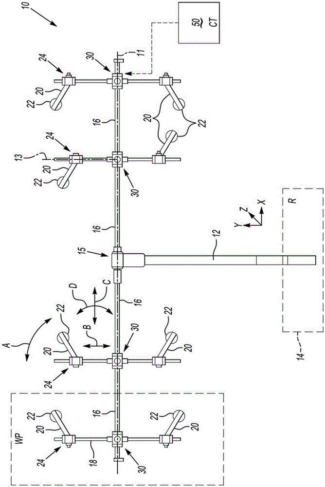
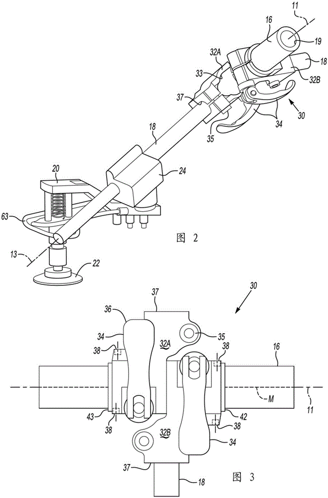
[0015] Referring to the drawings, wherein like reference numerals refer to like parts throughout, a reconfigurable end effector assembly 10 is schematically shown at figure 1 middle. End effector assembly 10 includes a main arm 12 connected via a T-fitting 15 or other suitable connector to a support arm 16 having a longitudinal axis 11 . The arm 16 may have an inner wall 19, such as figure 2 and 4 shown in . The main arm 12 can be positioned anywhere in the Cartesian (xyz) frame of reference (i.e., free space) as desired by the robot (R) 14, such as a multi-axis material handling robot of the type commonly used in manufacturing facilities for logistics purposes . As is well understood in the art, such a robot 14 is programmable, fixed to a stationary or movable base, and configured to position the main arm 12 with respect to the workpiece (WP) as desired.

[0016] The support arm 16 of the end effector assembly 10 extends orthogonally with respect to the main arm 12 thro...


PUM


Abstract

The reconfigurable end effector assembly includes a main arm, support arms and branches. Branches extend radially outward from the arms. A tandem branch joint assembly connects the branch to the arm and includes first and second branch joints, each of the first and second branch joints having a cam lock. Tool modules installed to branches are translatable and rotatable with respect to the branch. The joint assembly only rotates and slides about the longitudinal axis of the arm when the cam lock is released. The configuration tool has an actuator and a finger. The branch joints define openings that are engaged by the fingers. The tool includes a latch that engages the cam lock and clamps the cam lock and unclamps the cam lock. A flexible skirt assembly may be mounted to the arm and configured to route segments of conduit to each tool module.

Description

technical field [0001] The present disclosure relates to reconfigurable robotic end effector assemblies. Background technique [0002] Robotic end effectors are used in a variety of manufacturing processes to perform tasks on specified workpieces. An end effector may include a tooling module having an end tool that is designed to grip, transport, orient and release a workpiece. Some end effectors include a main arm that is grasped and moved by the material handling robot as needed. An end effector arm extends outwardly from the main arm. A plurality of branches extend radially outward from the arm to form an array of tool modules. [0003] Individual tool modules and end tooling can be manually adjusted to a desired position and orientation prior to performing a job task. Such an end effector may facilitate the manufacturing process. However, conventional designs for interconnecting multiple arms and branches and for routing power to the end tool may still be suboptimal...

Claims


Application Information

Patent Timeline
Patent Type & Authority Patents(China)
IPC IPC(8): B25J15/00B25J17/02
CPCB25J15/0061B25J15/0616Y10T403/32057
Inventor Y-T.林R.J.梅纳萨J.波勒斯L.伦格小约瑟夫.J.埃克尔
Owner GM GLOBAL TECH OPERATIONS LLC
Learn More