
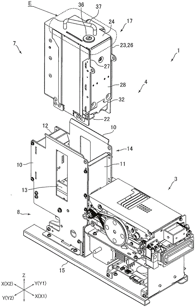
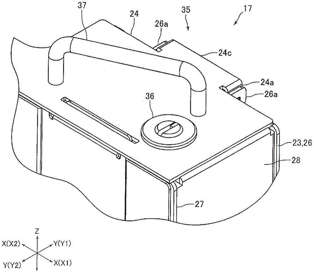
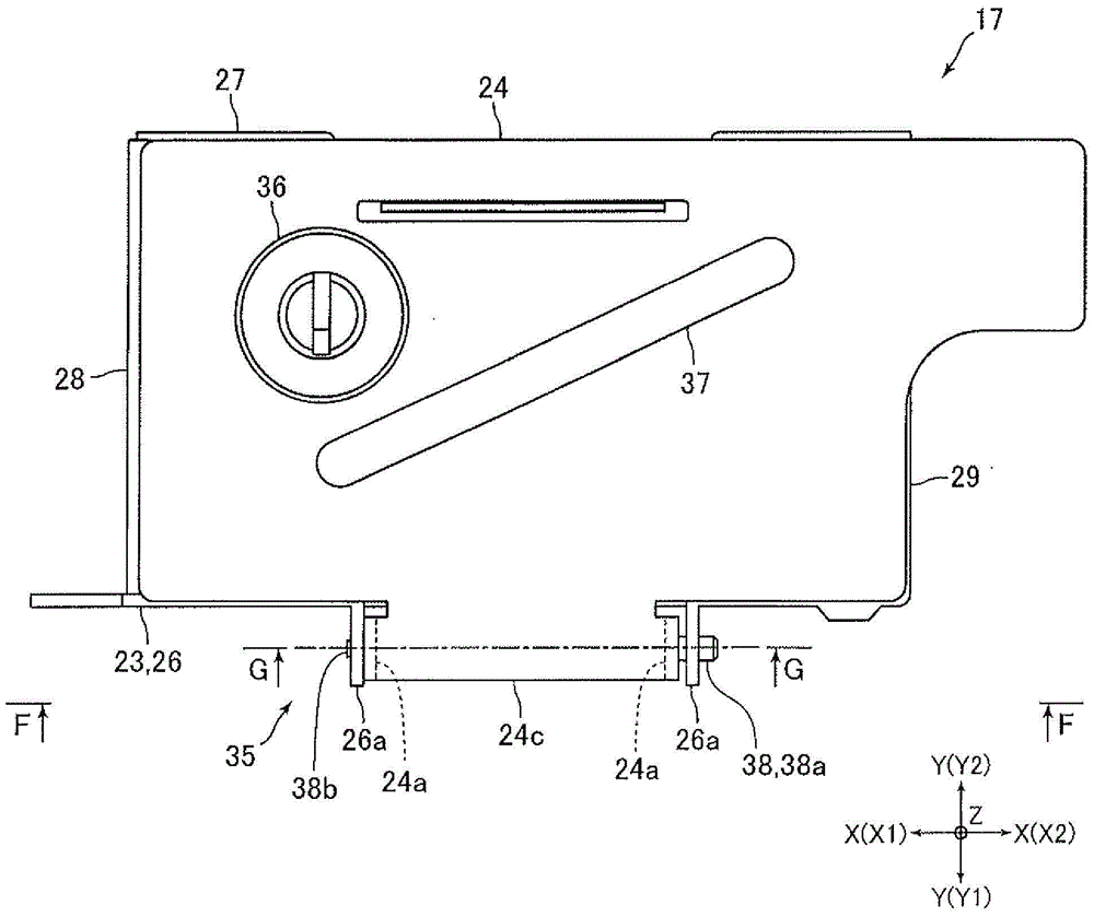
Card storage box and card issuing device

A technology for containing boxes and side panels, which is applied in the directions of transportation and packaging, separation of objects, separation of piles, etc., can solve problems such as deformation of the handle of the cover plate, replacement of the cover plate 102, etc., and achieve the effect of preventing illegally pulling out the card.

Inactive Publication Date: 2017-04-12
SANKYO SEIKI MFG CO LTD
View PDF5 Cites 0 Cited by
  • Summary
  • Abstract
  • Description
  • Claims
  • Application Information

AI Technical Summary

Problems solved by technology

On the other hand, the card storage box described in Patent Document 1 is sometimes taken out from the card issuing device and transported. Therefore, there may be defects such as deformation of the cover plate 102 and the handle due to vibration and impact when the card storage box is transported.
However, in the card storage box described in Patent Document 1, one end side of the hinge shaft 105 is caulked and fixed to the holding portion 101a. Therefore, when a defect occurs in the cover plate 102 or the handle, the cover plate 102 cannot be easily replaced.

Method used


Image

  • Card storage box and card issuing device
  • Card storage box and card issuing device
  • Card storage box and card issuing device

Examples


other Embodiment approach

[0086] The above-described embodiment is an example of preferred embodiments of the present invention, but the present invention is not limited thereto, and various modifications can be made without changing the technical idea of ​​the present invention.

[0087] In the above embodiment, the length of the sleeve 39 arranged between the two shaft holding parts 24a is slightly smaller than the distance between the two shaft holding parts 24a in the front-rear direction, and the locking screw 40 is used to prevent the hinge shaft 38 from facing each other. The sleeve 39 relatively moves in the front-back direction, thereby preventing the hinge shaft 38 from falling off in the front-back direction from the shaft holding portions 24a, 26a. In addition, for example, in the above-mentioned embodiment, the hinge shaft 38 can be prevented from going forward from the shaft holding parts 24a and 26a by using the stepped surface 38c formed on the hinge shaft 38 and the rear surface of the ...


PUM


Abstract

PROBLEM TO BE SOLVED: To provide a card storage cassette capable of preventing fraudulent extraction of a card even when replacement of a lid plate can be easily performed.SOLUTION: This card storage cassette has a hinge part 35 for connecting a side plate 23 and a lid plate 24 so that the lid plate 24 can be opened and closed. The hinge part 35 includes a hinge shaft 38 as a center of rotation for the lid plate 24. The side plate 23 is formed with a shaft holding part 26a formed with a shaft insertion hole 26b. The lid plate 24 is formed with a shaft holding part 24a formed with a shaft insertion hole 24b. The hinge part 35 further includes a falling off prevention screw 40 projected to the outside of a radial direction in order to prevent falling off of the hinge shaft 38 from the shaft holding parts 24a, 26a. This falling off prevention screw 40 is arranged inside the card storage cassette when the lid plate 24 is closed, and contacts the side plate 23 and the lid plate 24 so that the falling off prevention screw 40 is not exposed to the outside of the card storage cassette, and regulates a rotation range of the hinge shaft 38.

Description

technical field [0001] The present invention relates to a card storage case that stores a plurality of cards stacked on top of each other. In addition, the present invention also relates to a card issuing device including the above card storage box. Background technique [0002] Conventionally, there is known a card storage case that stores a plurality of cards in layers (for example, refer to Patent Document 1). The card storage case described in Patent Document 1 is used by being attached to a card issuing device. Additionally, if Figure 10 As shown, the card storage box includes: a side plate 101 that limits the four sides of the card and makes the cards neatly arranged in the vertical direction; The side plate 101 and the cover plate 102 are connected by a hinge portion 103 , and the cover plate 102 can be opened and closed relative to the side plate 101 . A lock 104 is installed on the cover plate 102 , and the lock 104 locks the cover plate 102 in such a way that t...

Claims


Application Information

Patent Timeline
Patent Type & Authority Patents(China)
IPC IPC(8): B65H1/04
Inventor 小口茂贵
Owner SANKYO SEIKI MFG CO LTD
Learn More