
Multi-optical axis photoelectric sensor

A photoelectric sensor, multi-optical axis technology, used in instruments, scientific instruments, photometry, etc.

Active Publication Date: 2014-12-24
KEYENCE
View PDF7 Cites 3 Cited by
  • Summary
  • Abstract
  • Description
  • Claims
  • Application Information

AI Technical Summary

Problems solved by technology

However, such components are a hindrance to size reduction and weight reduction of multi-optical axis photosensors

Method used


Image

  • Multi-optical axis photoelectric sensor
  • Multi-optical axis photoelectric sensor
  • Multi-optical axis photoelectric sensor

Examples


Embodiment

[0063] Hereinafter, preferred embodiments of the present invention will be described based on the drawings.

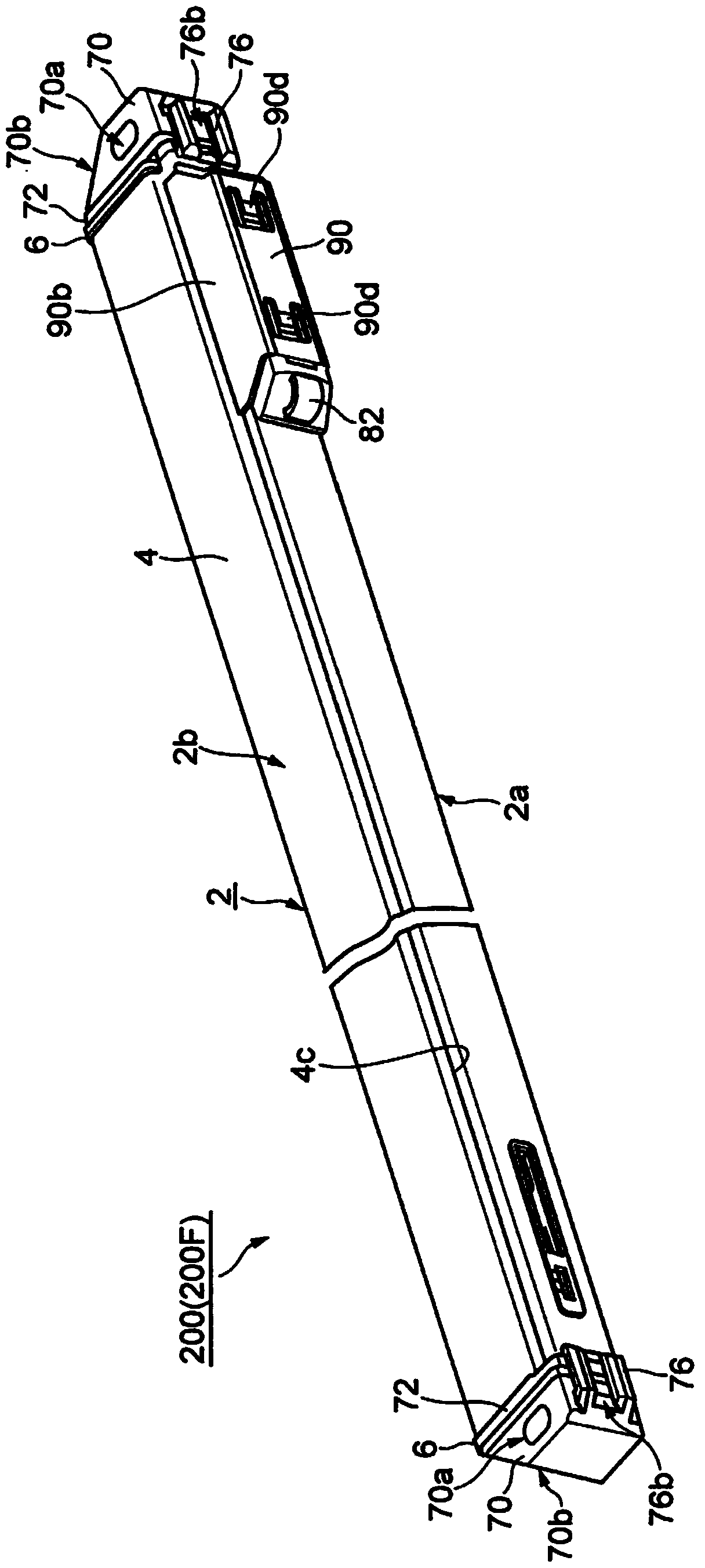
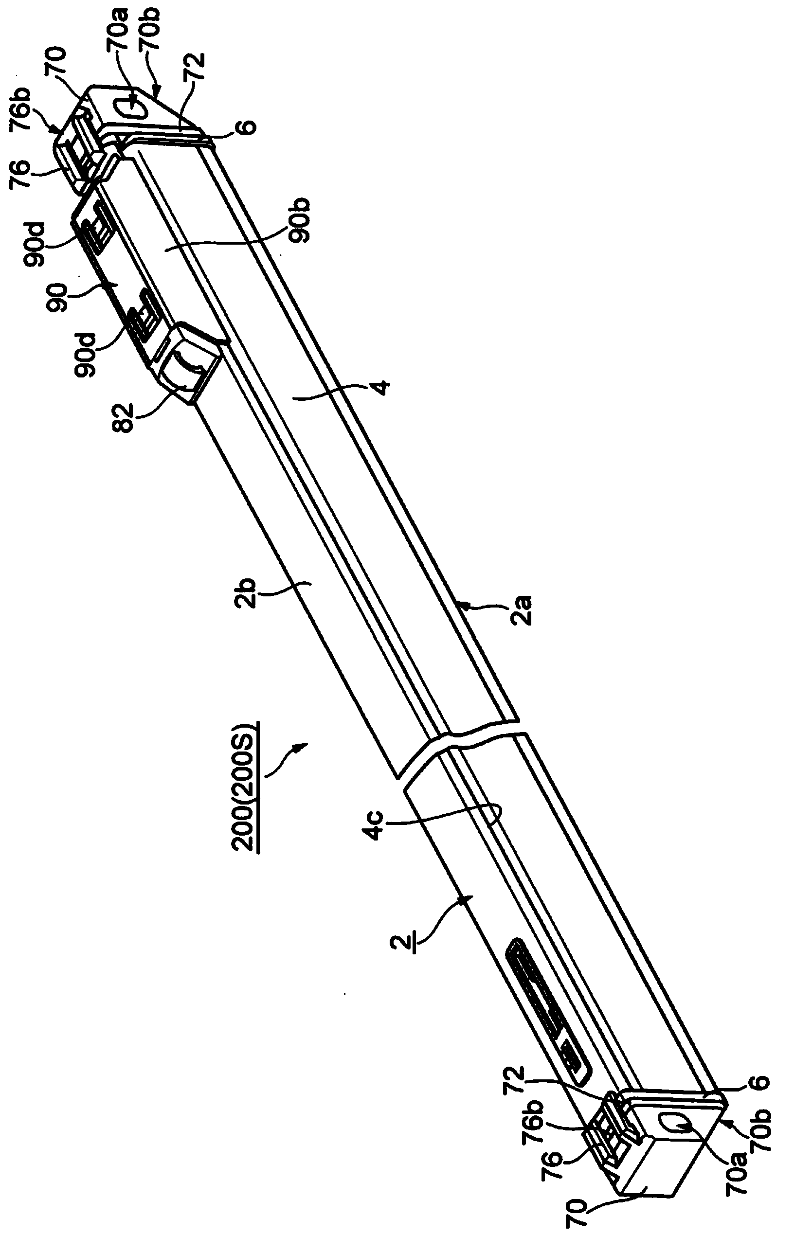
[0064] refer to figure 1 and figure 2 , the multi-optical axis photoelectric sensor 200 of the embodiment includes a housing 2 as a basic element. Two types of sensors 200F ( figure 1 ) and 200S ( figure 2 ).

[0065] available from figure 1 and figure 2 As seen in , the housing 2 has an elongated shape with a substantially rectangular cross-section. figure 1 The first sensor 200F uses a relatively wide surface corresponding to the long side of the rectangle as the light emitting / receiving surface 2a. The first sensor 200S uses a relatively narrow surface corresponding to the short side of the rectangle as the light emitting / receiving surface 2a. exist figure 1 and figure 2 In , the first sensor 200F and the second sensor 200S are shown as having a light emitting / receiving surface 2 a facing downward and a rear surface 2 b facing upward.

[0066] exist ...


PUM


Abstract

Provided is a multi-optical axis photoelectric sensor that can achieve downsizing and weight reduction. The multi-optical axis photoelectric sensor includes a case body which is formed to have open ends and has the same cross-sectional shape in a longitudinal direction of the multi-optical axis photoelectric sensor; end members which are attached to one end and the other end of the case body and each formed of a molded article for closing an opening on each of the ends; and an optical component which is arranged from one end to the other end of the case body so as to be separated from an inner face of the case body. The optical component has a function of defining the spread angle of each optical axes. The optical component and the end members are directly or indirectly physically engaged with each other to unrotatably position the optical component by the end members.

Description

technical field [0001] The invention relates to a multi-optical axis photoelectric sensor. Background technique [0002] Multi-axis photoelectric sensors are used as safety devices for monitoring access to hazardous areas. Multi-axis photoelectric sensors have multiple internal light-emitting elements or light-receiving elements. In addition, an optical member including a lens or the like is provided for each optical axis of these optical elements as a member for defining a divergence angle of each optical axis (divergence angle of detection light) (for example, JP8-45400A, JP2011-216372A, and JP2006 -107797A). [0003] JP8-45400A discloses a multi-optical axis photoelectric sensor employing a long main body housing which is a resin molded body. Specifically, the main body housing, which is a resin molded body, has detection windows for the respective optical axes, and lens members are bonded to the detection windows. In addition, an optical element (light receiving elem...

Claims


Application Information

Patent Timeline
Patent Type & Authority Applications(China)
IPC IPC(8): G01V8/20
CPCG01J1/0271G01V8/20
Inventor 石川要小山胜也利耶·塔塔·切亚
Owner KEYENCE
Features
  • Generate Ideas
  • Intellectual Property
  • Life Sciences
  • Materials
  • Tech Scout
  • Unparalleled Data Quality
  • Higher Quality Content
  • 60% Fewer Hallucinations
Learn More