
Power load balancing method for power transmission line

A technology for power loads and transmission lines, applied in the direction of circuit devices, AC network circuits, electrical components, etc., can solve problems such as inaccurate predictions, and achieve the effect of accurate load increments

Active Publication Date: 2014-12-24
SHANGHAI MUNICIPAL ELECTRIC POWER CO
View PDF4 Cites 1 Cited by
  • Summary
  • Abstract
  • Description
  • Claims
  • Application Information

AI Technical Summary

Problems solved by technology

However, the present invention does not take into account the natural growth of the power load of a single node, so its prediction is not very accurate

Method used


Image

  • Power load balancing method for power transmission line
  • Power load balancing method for power transmission line
  • Power load balancing method for power transmission line

Examples


Embodiment Construction

[0039] The present invention will be described in detail below in conjunction with the accompanying drawings and specific embodiments. This embodiment is carried out on the premise of the technical solution of the present invention, and detailed implementation and specific operation process are given, but the protection scope of the present invention is not limited to the following embodiments.

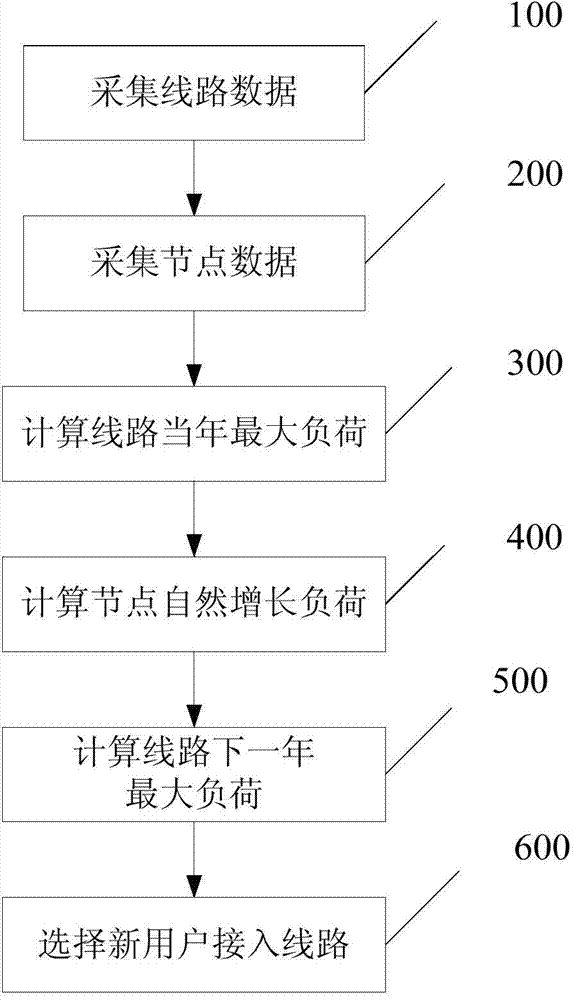
[0040] A method for power load balancing of transmission lines, such as figure 1 As shown, the method includes the steps of:

[0041] 100) Collecting the real-time current of the line, the voltage at the head end of the line and the real-time power factor;

[0042] It is possible to set up a line data acquisition device at the head end of the line, which collects line data such as real-time current, line head-end voltage, and real-time power factor, and sends them to the centralized control device.

[0043] 200) collecting the node type, node access time and node instant power of ea...


PUM


Abstract

The invention relates to a power load balancing method for a power transmission line. Th power load balancing method includes the steps: 100), collecting line instantaneous current, line head-end voltage and instantaneous power factor; 200), collecting node type, node access time and node instantaneous power of each existing node in the line; 300), acquiring maximum load of the line in the current year according to the collected line instantaneous current, line head-end voltage and instantaneous power factor; 400), acquiring existing node increase load according to the node type, the node access time and the node instantaneous power of the existing nodes and node load natural increase curve; 500), acquiring power load of the power line of the next year according to the maximum load of the power transmission line in the current year and the existing node increase load; 600), ordering the power load of lines of the next year, and selecting the line minimum in power load as an access line for new users. Compared with the prior art, the power load balancing method has the advantages of high operability and the like.

Description

technical field [0001] The invention relates to the field of power dispatching, in particular to a power load balancing method for transmission lines. Background technique [0002] The power system needs to rely on a unified dispatching command system to achieve normal adjustment and economic operation, as well as safety control, accident prevention and handling, etc. According to the scale of the power system, the dispatching command system is mostly established in layers, which not only divides responsibilities, but also unifies command and coordination, and adopts various automatic devices to establish an automatic dispatching system. [0003] Transmission lines are an important part of the power system, and their operating status directly affects the reliability and power quality of the power system. Therefore, it is of great significance to accurately predict the load of transmission lines to improve the operational reliability of the power system, but the existing tec...

Claims


Application Information

Patent Timeline
IPC IPC(8): H02J3/00
Inventor 程倩杨晨燕陆慧丰阙之玫仇成
Owner SHANGHAI MUNICIPAL ELECTRIC POWER CO
Learn More