Paper folding device

A paper stacking and paper feeding technology, applied in the direction of folding thin materials, transportation and packaging, function indication, etc., can solve a lot of time and other problems, and achieve the effect of easy resetting

Active Publication Date: 2014-12-24
HORIZON INTERNATIONAL INC
View PDF9 Cites 3 Cited by
  • Summary
  • Abstract
  • Description
  • Claims
  • Application Information

AI Technical Summary

Problems solved by technology

However, the work of resetting the position of such a stopper requires skilled technology and a lot of time.

Method used


Image

  • Paper folding device
  • Paper folding device
  • Paper folding device

Examples


Embodiment Construction

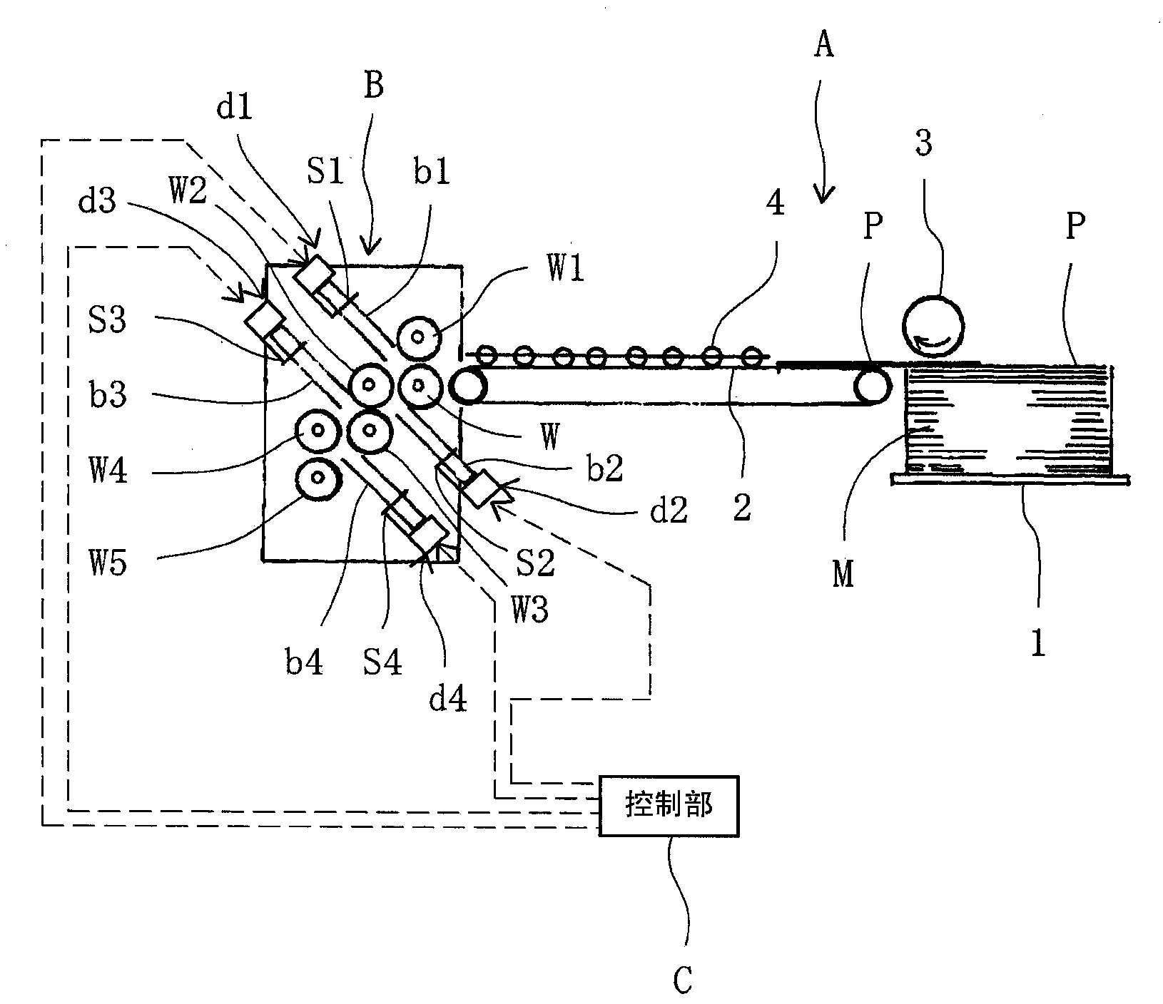
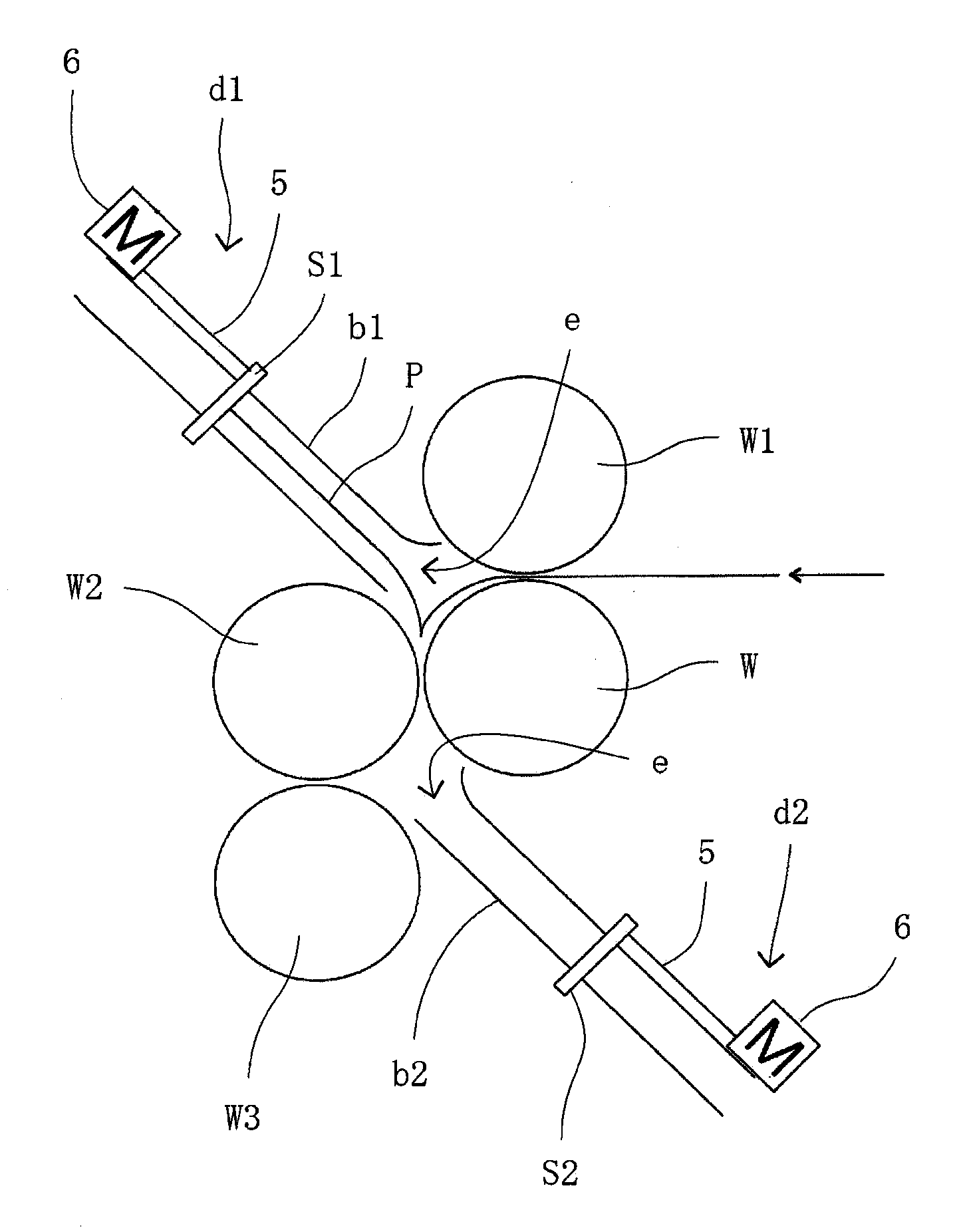
[0029] Hereinafter, preferred embodiments of the present invention will be described with reference to the drawings. figure 1 is a diagram showing a schematic configuration of an origami device according to an embodiment of the present invention, figure 2 yes means figure 1 An enlarged view of the structure of the folding section of the folding device shown.

[0030] refer to figure 1 The paper folding apparatus of the present invention includes a paper feeding unit A that sequentially feeds paper P from a paper pile M, and a paper folding unit B that folds the paper P fed from the paper feeding unit A at right angles to the paper feeding direction.

[0031] The paper supply unit A has: a shelf 1 on which a stack of paper M is placed and can be raised and lowered; a conveyor belt 2 extending between the shelf 1 and the folding unit B; The uppermost paper P is sequentially fed to the paper feeder 3 on the conveyor belt 2 . In this embodiment, the paper feeder 3 is compo...


PUM


Abstract

Buckles (b1 to b4) are each provided with a stopper (S1 to S4). A pair of uptake rollers (W, W1); (W, W2); (W2, W3); (W3, W4), to supply paper to the buckles, and a pair of discharge rollers (W, W2); (W2, W3); (W3; W4); (W4, W5), to fold the portion of the paper discharged outside the buckles, are disposed at each buckle inlet. The discharge roller for a previous buckle simultaneously functions as the uptake roller for the next buckle, and the paper is sequentially introduced into the buckles and folded into a bellows form. Stopper drive mechanisms (d1 to d4) are integrally controlled by a control unit (C). The control unit receives input for the value of the difference in length between the last folded piece and the remaining folded piece of a bellows-folded paper in which a folding error has occurred, divides the length difference by the number of buckles, and sends control instructions to slide the stoppers in the same direction as the buckle inlet (e) relative to the stopper drive mechanisms for the length obtained by division in order to make the length difference zero.

Description

technical field [0001] The present invention relates to a paper folding device, and more particularly to a paper folding device that alternately performs mountain folds and valley folds at right angles to a paper feeding direction to fold the paper into a corrugated shape. Background technique [0002] In the prior art, there is known a paper folding device configured to alternately perform mountain folds and valley folds on paper at right angles to the paper feeding direction by sandwiching the paper between a pair of paper folding rollers. , so that the paper is folded into a corrugated shape (for example, refer to Patent Documents 1 and 2). [0003] Figure 7 It is a figure which shows the schematic structure of this kind of origami apparatus. exist Figure 7 Among them, A represents the paper feeding part, B represents the conveying part, and C represents the paper folding part. The paper feeding unit A has a paper loading table 1 on which a paper bundle is placed and ...

Claims


Application Information

Patent Timeline
Patent Type & Authority Applications(China)
IPC IPC(8): B65H45/16
CPCB65H45/144B65H2511/11B65H2511/20B65H2220/01B65H2220/02B65H45/20
Inventor 井田辰章山本宏生渡边晋哉弗莱德汉姆·菲佛
Owner HORIZON INTERNATIONAL INC
Why Eureka
Try Eureka