Motor vehicle lighting device with a coupling lens and a transport and conversion lens

A technology for optical devices and lighting devices, which can be applied to lighting devices, fixed lighting devices, components of lighting devices, etc., and can solve the problems of not being oriented in parallel

Inactive Publication Date: 2014-12-31
AUTOMOTIVE LIGHTING REUTLINGEN GMBH
View PDF1 Cites 31 Cited by
  • Summary
  • Abstract
  • Description
  • Claims
  • Application Information

AI Technical Summary

Problems solved by technology

[0007] A major disadvantage of this type of light guide is that the light rays that impinge directly radially into the half-cavities facing the light exit surface do not impinge on the first mirror and are therefore not oriented parallel

Method used


Image

  • Motor vehicle lighting device with a coupling lens and a transport and conversion lens
  • Motor vehicle lighting device with a coupling lens and a transport and conversion lens
  • Motor vehicle lighting device with a coupling lens and a transport and conversion lens

Examples


Embodiment Construction

[0041] The same reference numbers in the various figures here indicate respectively identical or at least functionally similar elements.

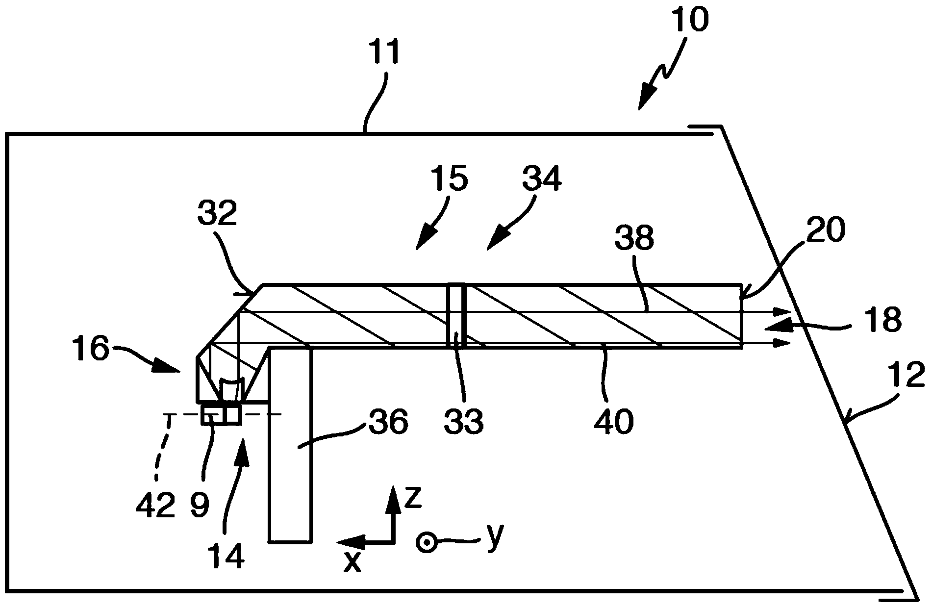
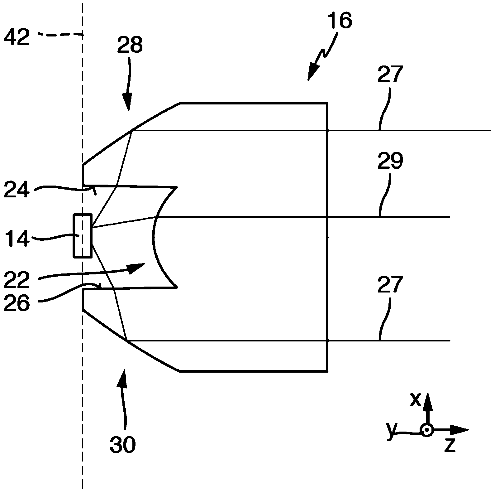
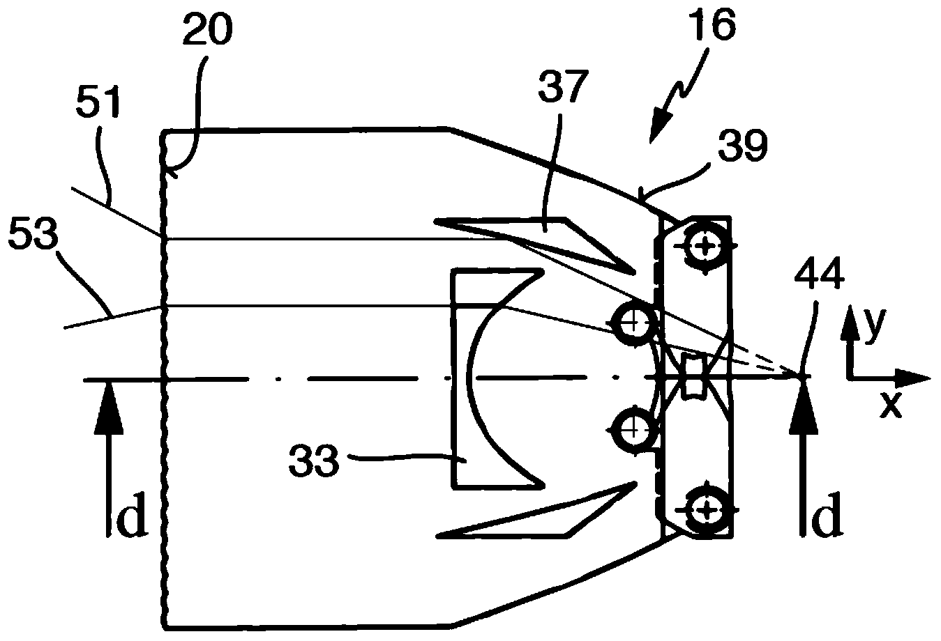
[0042] figure 1 Shown is a motor vehicle lighting device 10 with a housing 11 whose light exit opening is covered by a transparent dust cover 12 . The light source 14 held in a fixed position in the housing and the light guide arrangement 15 with the coupling optics 16 and the transmission and deformation optics 18 are located in the interior of the housing. Both the coupling optics 16 and the transmission and anamorphic optics 18 consist of a transparent light-conducting material, such as PC, PMMA, glass, COC or similar transparent materials, at least in the region in which they transmit the light from the light source 18 .

[0043]The transmission and anamorphic optics 18 have a light exit surface 20 at one end. The light source 14 is preferably a semiconductor light source, in particular a light emitting diode or a device consisting of...


PUM


Abstract

A motor vehicle lighting equipment with a light source and an optical fiber arrangement, having an input coupler and a transport and transformation lens system. The input coupler has a curved light beam forming surfaces, which reduces the angle of beam of the light in these second sectional planes when penetrating the surface. The transport and transformation lens system has transformation lenses which have a mutual focal point. The light source is located in the mutual focal point. The light source is arranged in such a way on the side of the optical fiber arrangement located opposite of the light-emitting surface that all areas of the optical fiber arrangement conducting light from the light source are located between the light source and the light-emitting surface, and the one planar deflection area is arranged between the curved surfaces of the input coupler and the transformation lenses.

Description

technical field [0001] The invention relates to a lighting device for a motor vehicle according to the preamble of claim 1 . Background technique [0002] Such motor vehicle lighting devices are known per se and have a light source and an optical waveguide arrangement with coupling optics and transmission and deformation optics. The transmission and anamorphic optics have a light exit surface, and the coupling optics are arranged to deform the light beam emitted from the light source and directed towards the transmission and anamorphic optics. The incoupling optics have at least one beam-forming and spatially curved surface, which in a first section has semicircular edges, the center of which is also arranged on the axis on which the light source is located, and the at least one surface in a second section It has a lenticular profile that reduces the angle of opening of the light rays in the second cross-section as they pass through the surface. The transmission and anamor...

Claims


Application Information

Patent Timeline
Patent Type & Authority Applications(China)
IPC IPC(8): F21S8/10F21V8/00F21V5/04F21W101/02F21W107/10
CPCG02B6/0018G02B6/002G02B6/003F21S43/14F21S43/27F21S43/26F21S43/239F21S43/241F21S43/243F21S43/315F21S43/40F21S41/24
Inventor M·格鲍尔D·肖特
Owner AUTOMOTIVE LIGHTING REUTLINGEN GMBH
Why Eureka
Try Eureka