
Display device, driving method for display device, and electronic device

A technology of a display device and a driving unit, which is applied to static indicators, instruments, etc., can solve problems such as the reduction of the contrast of the display panel, and achieve the effect of solving the reduction of the contrast ratio.

Inactive Publication Date: 2019-04-05
SONY CORP
View PDF6 Cites 0 Cited by
  • Summary
  • Abstract
  • Description
  • Claims
  • Application Information

AI Technical Summary

Problems solved by technology

As a result, a problem in which the contrast ratio of the display panel is lowered

Method used


Image

  • Display device, driving method for display device, and electronic device
  • Display device, driving method for display device, and electronic device
  • Display device, driving method for display device, and electronic device

Examples


Deformed example 1

[0136] In the above embodiments, the reference voltage V ref is set to use satisfying V ref >V dd -V th relationship voltage, but if the reference voltage V ref meet the above conditions, the reference voltage V ref can be with the pixel circuit 20 supply voltage V dd different voltages. However, it is preferred that the reference voltage V ref with supply voltage V dd same. By applying the reference voltage V ref set to supply voltage V dd same voltage, since there is no need to create a reference voltage for V ref Since a dedicated power supply is provided, it has the advantage of being able to simplify system configuration.

Deformed example 2

[0138] In the above embodiments, when the reference voltage V is used ref is applied to the signal line 33 when the signal voltage from the image signal V sig switch directly to the reference voltage V ref configuration, but can be employed where the applied reference voltage V ref Before, apply the signal voltage V sig with reference voltage V ref The intermediate voltage between V mid Configuration.

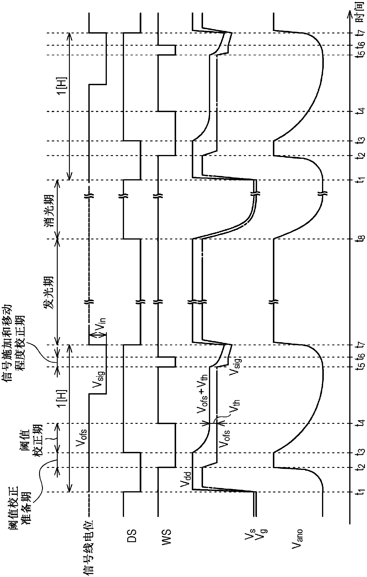
[0139] at the signal voltage from V sig switch directly to the reference voltage V ref case, as in Figure 9 shown in because the potential of the signal line 33 changes from V sig greatly shifts to V ref , so there is a case where an overshoot is generated in the potential of the signal line 33 . If an overshoot is generated during conversion, the gate potential V of the sampling transistor 23 in the non-conducting state of the organic EL element 21 light-emitting device g , drain potential V d and source potential V s (and the potential of the signal line 33) the...


PUM


Abstract

The present disclosure relates to a display device, a driving method for the display device, and electronic equipment. The display device includes: a pixel array unit, which is formed by arranging pixel circuits, and the pixel circuit has a P-channel drive transistor for driving the light emitting unit, a sampling transistor for applying a signal voltage, and a light emission control transistor for controlling the light emitting unit to emit light or not. , a storage capacitor connected between the gate electrode and the source electrode of the drive transistor, and an auxiliary capacitor connected to the source electrode; and a drive unit that applies the first voltage and the second voltage to the threshold correction period, respectively. The source electrode of the drive transistor and the gate electrode of the drive transistor, the difference between the first voltage and the second voltage is smaller than the threshold voltage of the drive transistor, and subsequently, when the source electrode is in a floating state, the threshold correction will be performed A standard voltage is applied to the gate electrode for driving.

Description

[0001] Cross References to Related Applications [0002] This application claims the benefit of Japanese Priority Patent Application JP2013-142831 filed on Jul. 8, 2013, the entire contents of which are incorporated herein by reference. technical field [0003] The present disclosure relates to a display device, a driving method for the display device, and an electronic device, and in particular, to a planar type (panel type) display device formed of pixels including light emitting units arranged in rows and columns (matrix form), a A driving method for a display device and an electronic device including the display device. Background technique [0004] A display device using a so-called current-driven photoelectric element in which light emission luminance is changed according to a value of current flowing to a light emitting unit (light emitting element) that is a light emitting unit of a pixel is a flat type display device. For example, an organic electroluminescence (EL...

Claims


Application Information

Patent Timeline
Patent Type & Authority Patents(China)
IPC IPC(8): G09G3/30
CPCG09G2300/0819G09G2300/0852G09G2300/0861G09G2320/0238G09G2320/045G09G3/3233
Inventor 小野山有亮山下淳一丰村直史
Owner SONY CORP
Learn More