
Shift control device for vehicle

一种控制装置、车辆的技术,应用在发动机控制、传动装置控制、带有齿的元件等方向,能够解决变速冲击、离合器耐久性降低、工时或者作业变多等问题,达到防止变速冲击、降低变速冲击、削减工时的效果

Active Publication Date: 2015-01-14
TOYOTA JIDOSHA KK
View PDF8 Cites 9 Cited by
  • Summary
  • Abstract
  • Description
  • Claims
  • Application Information

AI Technical Summary

Problems solved by technology

Therefore, the torque capacity of these clutches or the control of the hydraulic pressure becomes discontinuous, which becomes a factor, and there is a possibility that a shift shock may occur.
In addition, since the torque capacity of the release side clutch is determined in advance so that it becomes zero at the start time of the inertia phase, it is inappropriate to increase man-hours or work for this purpose.
Furthermore, since the torque capacity of the release-side clutch is set based on the target output torque, if the accelerator opening changes during shifting and the target output torque changes accordingly, it is necessary to reset the release-side clutch at this point in time. The torque capacity of the clutch, therefore, there is a possibility that a shift shock due to a delay in control occurs, or the control system or control software becomes complicated.
[0007] In addition, the device described in Japanese Patent Application Laid-Open No. 2001-227637 is a device configured to control the clutch on the meshing side in the torque phase of the clutch-to-clutch shift, and actively generates changes in the rotational speed of the rotating parts including the engine in the inertia phase. , so the device described in Japanese Patent Application Laid-Open No. 2001-227637 cannot be applied to the overall control of clutch-to-clutch speed change
[0008] In addition, the device described in Japanese Patent Application Laid-Open No. 2008-025637 is a device for simplifying downshift control, so it cannot be applied to all shift modes from clutch to clutch shift including upshift, and because the clutch on the release side Control is in a so-called slip state, and shift control is performed in this state, so there is a possibility that the wear of the clutch will progress and the durability will decrease.

Method used

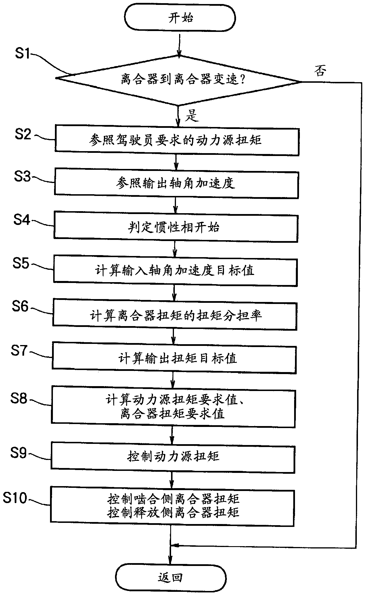
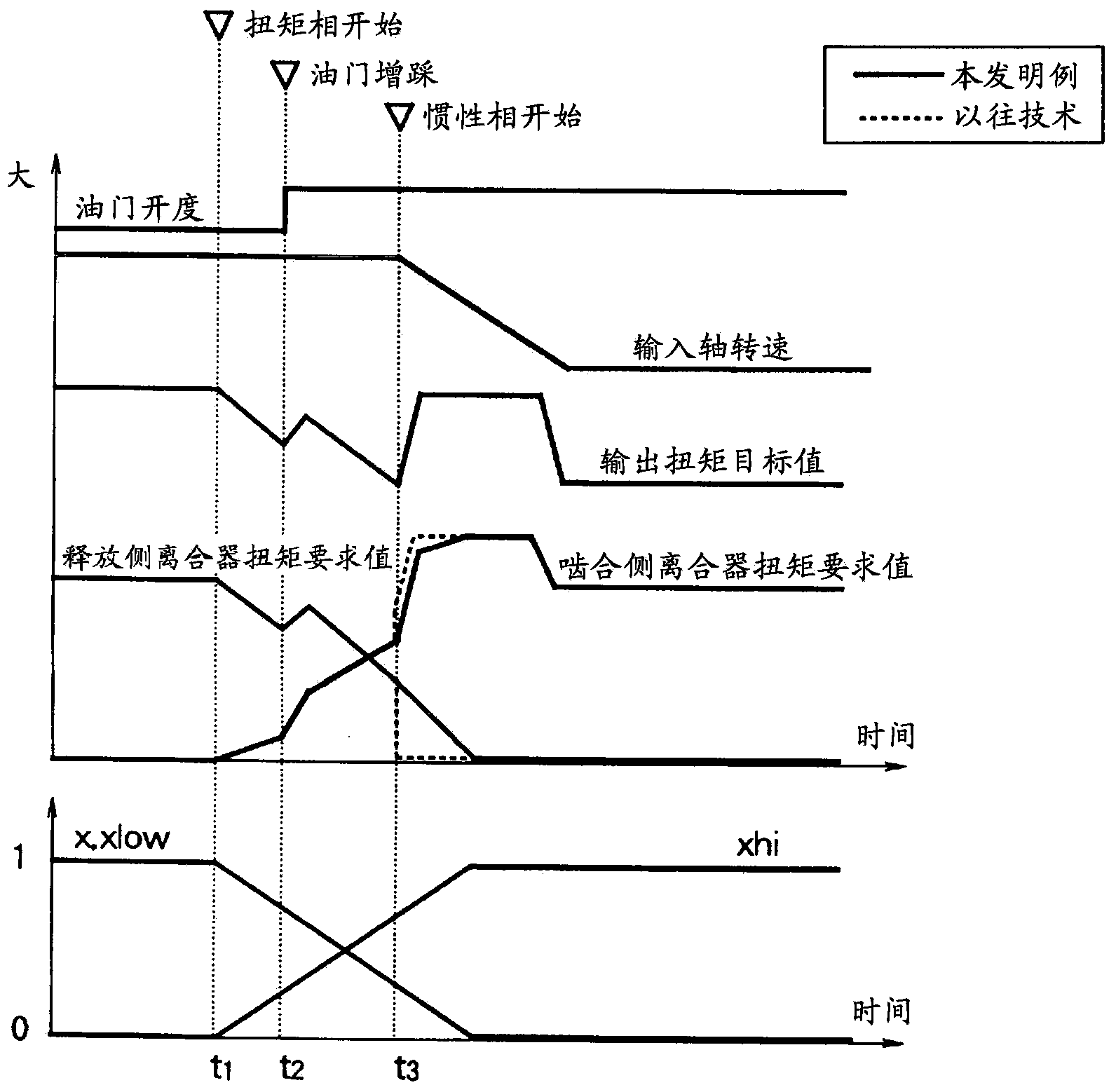
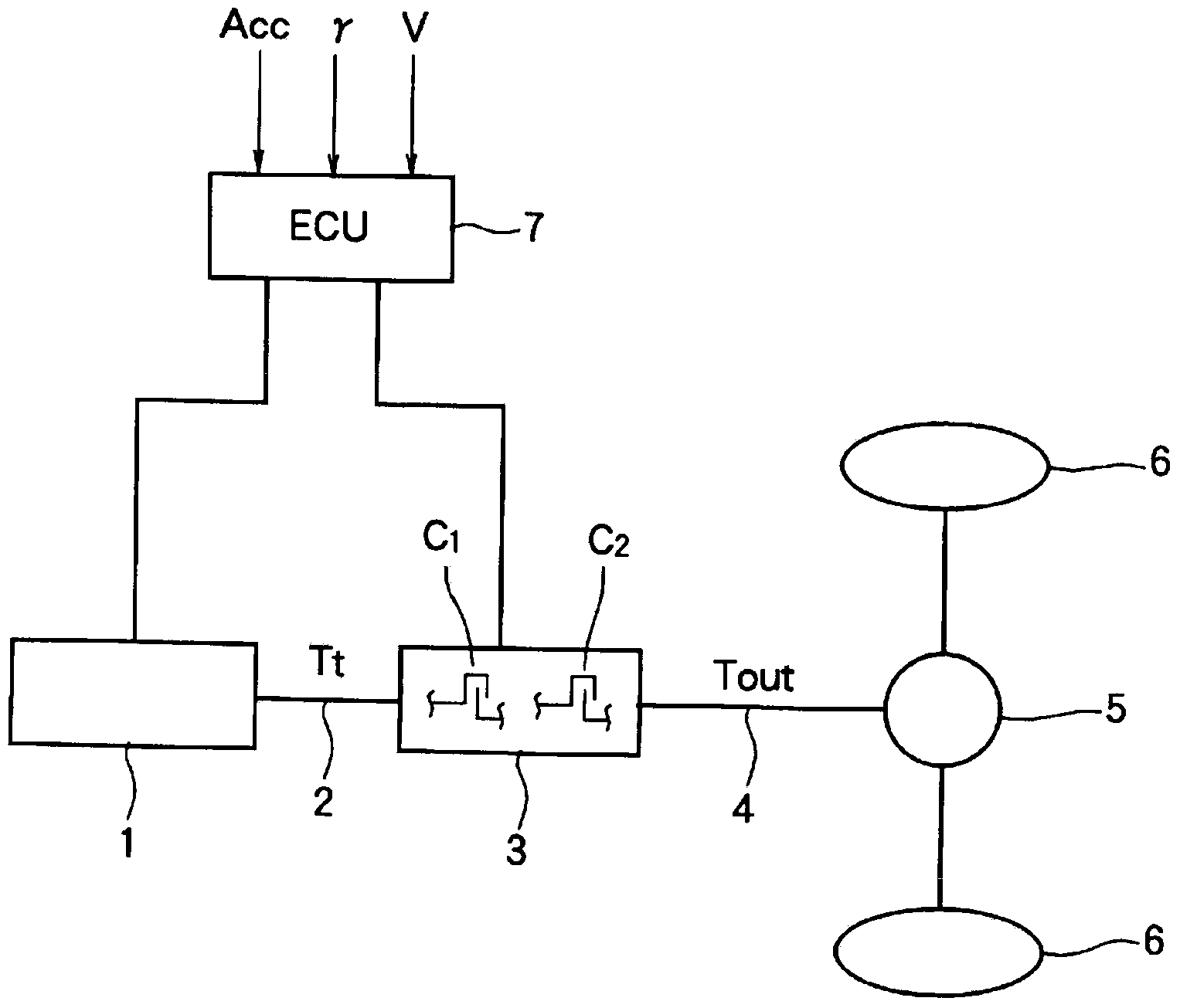

Image

  • Shift control device for vehicle
  • Shift control device for vehicle
  • Shift control device for vehicle

Examples


Embodiment Construction

[0020] First, when describing a vehicle that can be a target of the present invention, the vehicle that is a target of the present invention is a vehicle equipped with an automatic transmission that performs clutch-to-clutch shifting. If it is schematically shown in a block diagram as image 3As shown, an automatic transmission 3 is connected to an output side of a power source 1 via an input shaft 2 . The power source 1 is constituted by an internal combustion engine such as a gasoline engine or a diesel engine, or a motor, or a hybrid power source combining an internal combustion engine and a motor. The power source 1 is configured to electrically control at least output torque. For example, if it is a gasoline engine, it is equipped with an electronic throttle valve, and is configured to electrically control the throttle opening to set the output torque corresponding to the amount of intake air, and to perform retard angle control or advanced angle control of the ignition ...


PUM


Abstract

Provided is a shift control device for a vehicle, constructed so as to reduce shift shocks in clutch-to-clutch shifting. With a transmission, for which multiple gear ranges are set in accordance with the engagement and release states of multiple engagement mechanism capable of continuously changing the torque capacity, being connected to the output side of a power supply, this shift control device for a vehicle performs clutch-to-clutch shifting that switches from a prescribed gear range to another gear range by gradually reducing the torque capacity of a prescribed engagement mechanism so as to release the prescribed engagement mechanism and gradually increasing the torque capacity of another engagement mechanism so as to engage this other engagement mechanism. In addition, this shift control device for a vehicle is equipped with: an output shaft torque calculation means (step S7) that calculates a target value for the output shaft torque of the transmission on the basis of the input shaft torque for the transmission, which is based on a driving amount requested by the driver, the angular acceleration of the input shaft of the transmission, the angular acceleration of the output shaft of the transmission, and the torque shares of the engagement-side engagement mechanism and the release-side engagement mechanism; and a torque capacity calculation means (step S8) that calculates the torque capacities for the engagement-side engagement mechanism and the release-side engagement mechanism in the torque phase and the inertia phase during clutch-to-clutch shifting, on the basis of the target value for the output shaft torque, the angular acceleration of the input shaft of the transmission, the angular acceleration of the output shaft of the transmission, and the torque shares of the engagement-side engagement mechanism and the release-side engagement mechanism.

Description

technical field [0001] The present invention relates to a device for controlling gear shifting in a vehicle, and more particularly to a device for performing gear shift control for changing gear stages by simultaneously releasing and engaging engagement mechanisms such as clutches and brakes. Background technique [0002] The gear ratio of a vehicle is determined by the mechanism that participates in the transmission of torque from a driving force source such as an engine to the driving wheels. A conventional general vehicle transmission is configured by selecting a gear that participates in torque transmission from a plurality of gear pairs through a clutch. Yes, or according to the engagement and release states of clutches, brakes and other engagement mechanisms, select the torque transmission path in the transmission mechanism composed of multiple sets of planetary gear mechanisms, and switch according to the engagement and release states of clutches, brakes and other enga...

Claims


Application Information

Patent Timeline
Patent Type & Authority Applications(China)
IPC IPC(8): F16H61/06B60W10/04B60W10/11F02D29/00
CPCB60W2710/105F16H2059/405F16H61/684F16H61/06F16H2059/425B60W30/19B60W10/04B60W10/06B60W10/11B60W2710/0666B60W2710/1005F02D29/02F16H61/061F16H2302/00F16H2306/42
Inventor 增永圣二长谷川善雄桑原清二小林宽英
Owner TOYOTA JIDOSHA KK
Learn More