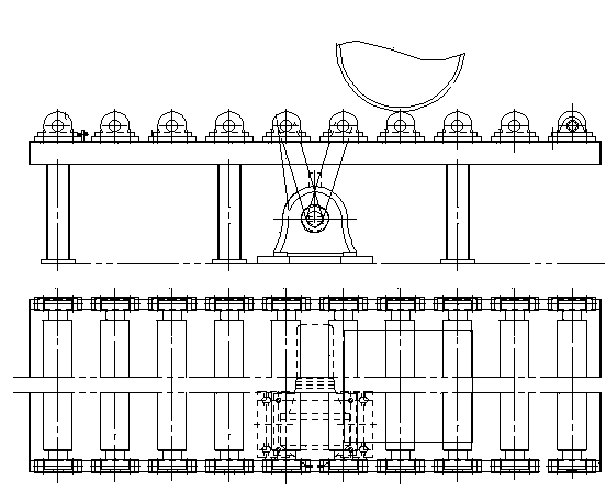
Workpiece discharging roller way of coiling machine
A technology of coiler and discharge roller, which is applied in the direction of roller table, manufacturing tools, metal processing equipment, etc. It can solve the problems that the spiral workpiece cannot be conveyed, the roller table cannot provide support, and the spiral pipe cannot be supported and conveyed. Achieve the effect of smooth transition, stable transmission and high efficiency
- Summary
- Abstract
- Description
- Claims
- Application Information
AI Technical Summary
Problems solved by technology
Method used
Image
Examples
Embodiment 1
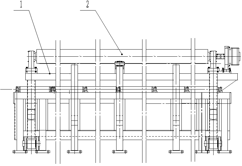
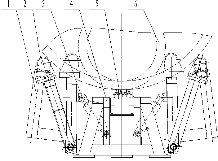
[0019] Such as Figure 2-Figure 4 As shown, the workpiece discharge roller table of the coiler includes a fixed support roller bracket 5, two movable support brackets 1, a plurality of movable supports and a plurality of fixed support rollers 8, and the plurality of fixed support rollers 8 are transported along the workpiece 7 The direction is uniformly inclined and arranged on the top of the horizontal fixed support roller bracket 5, and the two movable support brackets 1 are symmetrically distributed on both sides of the fixed support roller bracket 5 along the conveying direction of the workpiece 7, and the plurality of movable supports are arranged along the conveying direction of the workpiece 7 Evenly distributed on the two movable support brackets 1, the structure of the movable support is: including the movable support roller 3 and the movable support cylinder 4, the cylinder body of the movable support cylinder 4 is hinged on the bottom of the fixed support roller brac...
Embodiment 2
[0024] Such as Figure 2-Figure 4 As shown, the workpiece discharge roller table of the coiler includes a fixed support roller bracket 5, two movable support brackets 1, a plurality of movable supports and a plurality of fixed support rollers 8, and the plurality of fixed support rollers 8 are transported along the workpiece 7 The direction is uniformly inclined and arranged on the top of the horizontal fixed support roller bracket 5, and the two movable support brackets 1 are symmetrically distributed on both sides of the fixed support roller bracket 5 along the conveying direction of the workpiece 7, and the plurality of movable supports are arranged along the conveying direction of the workpiece 7 Evenly distributed on the two movable support brackets 1, the structure of the movable support is: including the movable support roller 3 and the movable support cylinder 4, the cylinder body of the movable support cylinder 4 is hinged on the bottom of the fixed support roller brac...
Embodiment 3
[0030] Such as Figure 2-Figure 4 As shown, the workpiece discharge roller table of the coiler includes a fixed support roller bracket 5, two movable support brackets 1, a plurality of movable supports and a plurality of fixed support rollers 8, and the plurality of fixed support rollers 8 are transported along the workpiece 7 The direction is uniformly inclined and arranged on the top of the horizontal fixed support roller bracket 5, and the two movable support brackets 1 are symmetrically distributed on both sides of the fixed support roller bracket 5 along the conveying direction of the workpiece 7, and the plurality of movable supports are arranged along the conveying direction of the workpiece 7 Evenly distributed on the two movable support brackets 1, the structure of the movable support is: including the movable support roller 3 and the movable support cylinder 4, the cylinder body of the movable support cylinder 4 is hinged on the bottom of the fixed support roller brac...
PUM
 Abstract
Description
Claims
Application Information
 - R&D
- Intellectual Property
- Life Sciences
- Materials
- Tech Scout
- Unparalleled Data Quality
- Higher Quality Content
- 60% Fewer Hallucinations
Browse by: Latest US Patents, China's latest patents, Technical Efficacy Thesaurus, Application Domain, Technology Topic, Popular Technical Reports.
© 2025 PatSnap. All rights reserved.Legal|Privacy policy|Modern Slavery Act Transparency Statement|Sitemap|About US| Contact US: help@patsnap.com


