A kind of meat skin cutting machine

A flower cutting machine and meat skin technology, which can be used in cutting meat skin equipment and other directions, can solve the problems of large workload, a lot of manpower and material resources, complicated steps, etc., and achieve the effect of improved work efficiency, consistent cutting depth, and flexible operation.

Inactive Publication Date: 2016-01-06
黑龙江技师学院
View PDF8 Cites 0 Cited by
  • Summary
  • Abstract
  • Description
  • Claims
  • Application Information

AI Technical Summary

Problems solved by technology

[0003] The purpose of the present invention is to provide a meat skin flower cutting machine to solve the problem of heavy workload and cumbersome steps requiring a lot of manpower and material resources when cutting flowers on meat skin

Method used


Image

  • A kind of meat skin cutting machine
  • A kind of meat skin cutting machine
  • A kind of meat skin cutting machine

Examples


specific Embodiment approach 1

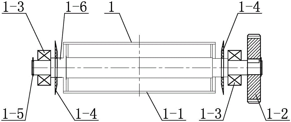
[0012] Specific implementation mode one: combine figure 1 , figure 2 , image 3 , Figure 4 , Figure 5 , Figure 6 , Figure 7 , Figure 8 , Figure 9 , Figure 10 , Figure 11 and Figure 12 Describe this embodiment, a kind of meat skin cutting flower machine described in this embodiment comprises roller body 1, the first disk blade group 2, the second disk blade group 3, the first comb body 4, the second comb body 5 and machine Frame 6, the roller body 1, the first disc blade group 2, the second disc blade group 3, the first comb body 4 and the second comb body 5 are all located in the frame 6, and the first disc blade group 2 is arranged horizontally with the roller body 1, the second disk blade group 3 is located below the roller body 1 and is provided with a gap with the roller body 1, and the first comb body 4 is arranged near the first disk blade group 2 and Set with the gap of the first disc blade set 2, the second comb plate body 5 is arranged near the se...

specific Embodiment approach 2

[0018] Specific implementation mode two: combination figure 1 , figure 2 , image 3 , Figure 4 , Figure 5 , Figure 6 , Figure 7 , Figure 8 , Figure 9 , Figure 10 , Figure 11 and Figure 12 Describe this embodiment, in this embodiment, the first comb body 4 includes a first carding main body 4-1 and a plurality of first combing teeth 4-2, which are evenly distributed on the first carding main body 4-1. A plurality of first combing teeth 4-2, the two ends of the first carding main body 4-1 are detachably connected on the frame 6; the second combing body 5 includes the second carding main body 5-1 and a plurality of The second carding teeth 5-2, a plurality of second carding teeth 5-2 evenly distributed on the second carding main body 5-1, the two ends of the second carding main body 5-1 are detachably connected on the frame 6 . The second comb body 5 is arranged between the outlet of the frame 6 and the second disc blade set 3 and close to the second disc bl...

specific Embodiment approach 3

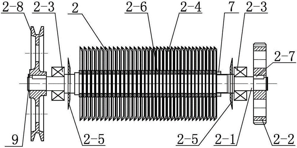
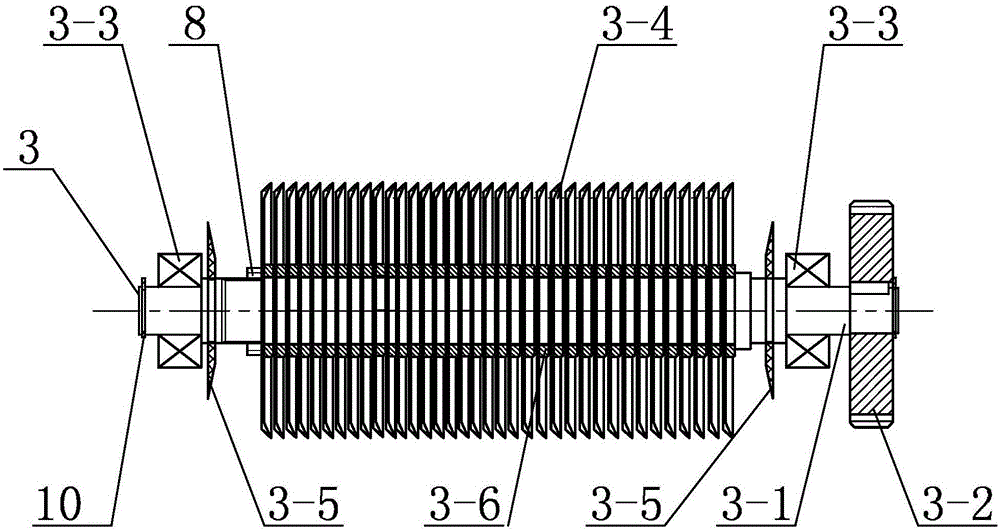
[0019] Specific implementation mode three: combination figure 1 , figure 2 , image 3 , Figure 4 , Figure 5 , Figure 6 , Figure 7 , Figure 8 , Figure 9 , Figure 10 , Figure 11 and Figure 12 Describe this embodiment, the first disk blade set 2 in this embodiment also includes two first dustproof rings 2-5, and the second disk blade set 3 also includes two second dustproof rings 3-5 , the two first dust-proof rings 2-5 are set on the first rotating shaft 2-1 and located on both sides of a plurality of first disk blades 2-4; the two second dust-proof rings 3- 5 are set on the second rotating shaft 3-1 and located on both sides of the plurality of second disc blades 3-4. In this embodiment, the setting of the two first dust-proof rings 2-5 is to prevent other particles such as dust from entering the plurality of first disk blades 2-4 when the first rotating shaft 2-1 rotates to cut the meat skin. A plate of blades 2-4 affects the normal use of multiple first ...


PUM


Abstract

The invention relates to a mixed cutting machine, in particular to a pork skin mixed cutting machine, which aims to solve the problems of pork skin mixed cutting such as high workload, complicated procedures, and large consumption of manpower and material resources. A roller body, a first disc blade assembly, a second disc blade assembly, a first comb plate body and a second comb plate body are all located in a frame; the first disc blade assembly is horizontally arranged in parallel with the roller body; the second disc blade assembly is located below the roller body and spaced from the roller body; the first comb plate body is arranged near to the first disc blade assembly and spaced from the first disc blade assembly; the second comb plate body is arranged near to the second disc blade assembly and spaced from the second disc blade assembly; the first disc blade assembly includes a first rotating shaft, a first gear, two first bearings, a first belt pulley and a plurality of first disc blades; the second disc blade assembly includes a second rotating shaft, a second gear, two second bearings and a plurality of second disc blades. The pork skin mixed cutting machine provided by the invention is used for cutting pork skin.

Description

technical field [0001] The invention specifically relates to a meat skin flower cutting machine, which belongs to the field of food cutting and processing machinery. Background technique [0002] With the vigorous development of my country's tourism and catering industries, the requirements for diversification in scale and form are getting higher and higher, and the requirements for nutrition, beauty and other content are also showing a growing trend. Solving these problems by developing and improving food machinery has become a trend of sustainable circulation. At present, star-rated hotels, catering centers, tourist attractions, food wholesale markets, citizens' daily life and other consumption places and consumer groups in open coastal cities are quietly changing with each passing day. In order to meet these needs, mainly through the blending of semi-finished products, the catering can meet the requirements of fastness and variety. However, the traditional technology is...

Claims


Application Information

Patent Timeline
Patent Type & Authority Patents(China)
IPC IPC(8): A22C17/12
CPCA22C17/12
Inventor 秦士宝王峰李德信王凤伟杨志颖张利凯崔建鑫米佰坤路久荣
Owner 黑龙江技师学院
Why Eureka
Try Eureka