Bidirectional rolling shaft limited foldable pneumatic curtain bracket

A foldable and movable bracket technology, applied in the field of curtains, can solve the problems of damage to curtain rings and hooks, increase structural complexity, increase installation costs, etc., and achieve the effects of avoiding breakage and disconnection, low processing costs, and increased efficiency.

Active Publication Date: 2015-01-28
启东市清源环境检测技术有限公司
View PDF5 Cites 6 Cited by
  • Summary
  • Abstract
  • Description
  • Claims
  • Application Information

AI Technical Summary

Problems solved by technology

[0002] At present, the more conventional curtain structure is to set a chute on the upper edge of the window, and a plurality of hooks are slidably fitted in the chute, and the buckles on the curtain body are hung on the respective corresponding hooks in sequence, thus by catching Hold the curtain body, and swing the curtain body to realize the opening and closing of the curtain, but the force exerted by the above-mentioned man grasping the curtain is not only the force used to open and close the curtain in the horizontal direction, but also the force to pull the curtain downward, so it needs to be applied by personnel. Large force, which not only causes inconvenience to open and close the curtain, but also causes damage to the buckle and hook on the upper end of the curtain after excessive pulling force or long-term use
[0003] In the prior art, although there are some automated curtains in which the motor drives the cable and finally directly drives the hook to slide, the process of the above-mentioned motor driving the cable not only has the risk of the cable breaking or the connection end being disengaged, but also the cable stretching. Both the cable channel and the storage mechanism are required during the storage and storage process, which further increases the structural complexity and increases the installation cost

Method used


Image

  • Bidirectional rolling shaft limited foldable pneumatic curtain bracket
  • Bidirectional rolling shaft limited foldable pneumatic curtain bracket
  • Bidirectional rolling shaft limited foldable pneumatic curtain bracket

Examples


Embodiment Construction

[0022] The present invention will be further described below in conjunction with the accompanying drawings and specific embodiments.

[0023] The said air pump realizes inflation and air extraction refers to connecting with the output end of the air pump through a reversing valve, thereby realizing the conversion of air extraction and air inflation.

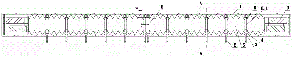
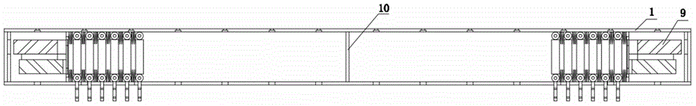
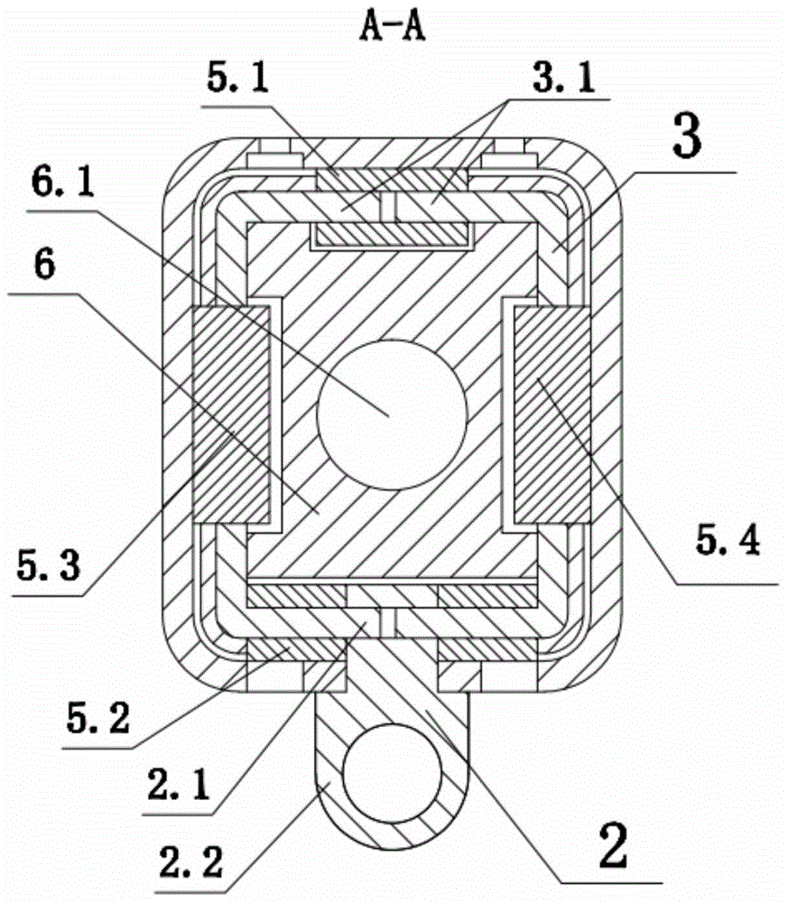
[0024] As shown in the figure, the present invention provides a two-way roller limit folding pneumatic curtain bracket, which includes a groove rail 1, a hook 2 that is slidably fitted on the groove rail 1 for hanging curtains, and is used to drive the hook 2 along the groove The driving mechanism that slides along the length direction of the rail 1, the grooved rail 1 is a hollow structure, and there are two driving mechanisms, and the two driving mechanisms are symmetrically arranged at both ends of the grooved rail 1, and each driving mechanism includes a respective uniform There are air pumps 9 with inflation and air extracti...


PUM


Abstract

The invention discloses a bidirectional rolling shaft limited foldable pneumatic curtain bracket. The bidirectional rolling shaft limited foldable pneumatic curtain bracket comprises a grooved rail, hooks and driving mechanisms, and is characterized in that the grooved rail is of a hollow structure; two driving mechanisms are symmetrically arranged at the two ends of the grooved rail; each driving mechanism comprises respective air pump and a plurality of movable brackets; an elastic corrugated pipe is arranged between any two adjacent movable brackets in the movable brackets which correspond to each air pump; the movable brackets are provided with air supply channels for communicating two adjacent elastic corrugated pipes; all the elastic corrugated pipes and air supply channels are fixed together and communicated into a telescopic air cavity of which one end is enclosed; the other end of the telescopic air cavity is communicated with the air pumps; the upper ends of the hooks are connected with the lower ends of the movable brackets; the lower ends of the hooks extend out of the grooved rail. The bidirectional rolling shaft limited foldable pneumatic curtain bracket is stable and reliable, is simple in structure, and is low in mounting cost.

Description

technical field [0001] The invention relates to the technical field of curtains, in particular to a pneumatic curtain support structure. Background technique [0002] At present, the more conventional curtain structure is to set a chute on the upper edge of the window, and a plurality of hooks are slidably fitted in the chute, and the buckles on the curtain body are hung on the respective corresponding hooks in sequence, thus by catching Hold the curtain body, and swing the curtain body to realize the opening and closing of the curtain, but the force exerted by the above-mentioned man grasping the curtain is not only the force used to open and close the curtain in the horizontal direction, but also the force to pull the curtain downward, so it needs to be applied by personnel. Large force, which not only causes inconvenience to opening and closing the curtain, but also causes damage to the buckle and hook on the upper end of the curtain after excessive pulling force or long-...

Claims


Application Information

Patent Timeline
IPC IPC(8): A47H1/02
CPCA47H1/04A47H5/02A47H13/04
Inventor 陆昱森
Owner 启东市清源环境检测技术有限公司
Why Eureka
Try Eureka