Remote monitoring system for elevator

A remote monitoring system and remote monitoring technology, applied in elevators, transportation and packaging, etc., can solve problems such as poor timeliness and reliability, neglect of alarms, and the need for manual alarms, etc., to achieve the effect of ensuring safe operation and convenient discovery

Inactive Publication Date: 2015-01-28
IFE ELEVATORS
7 Cites 28 Cited by

AI-Extracted Technical Summary

Problems solved by technology

[0003] At present, when the elevator breaks down, security personnel need to contact the maintenance personnel for maintenance; or when the user is trapped in the elevator, the user can also press the emergency call button in the elevator to call the police. The emergency call button is conn...

Method used

In addition, data docking module 28 is connected with ERP system server 43, and promptly remote monitoring server 1 can carry out data interaction with ERP management system, has realized automatic new addition, maintenance elevator basic information, automatically compiles the elevator ID associated with server function. Usually, in the elevator remote monitoring system 100, if the remote monitoring function needs to be installed, the basic information of the elevator to be monitored must first be added to the remote monitoring server 1, and then the remote monitoring terminal is installed on the corresponding elevator. However, adding the basic information of the elevator on the remote monitor...

Abstract

The invention discloses a remote monitoring system for an elevator. The remote monitoring system comprises a plurality of elevator control systems, corresponding remote monitoring terminals, an operator server, a remote monitoring server, a short message server and an email server, wherein the remote monitoring server comprises a receiving storage module and an alarm module; the alarm module is connected with the short message server and the email server and is used for sending an alarm short message and an alarm email to a worker through the short message server and the email server respectively when elevator data is alarm information. Compared with the prior art, the remote monitoring system has the characteristics that the remote monitoring terminals can be used for acquiring the elevator data in real time and uploading the elevator data to the remote monitoring server, the remote monitoring server can be used for automatically sending the alarm short message and the alarm email to the worker when the elevator has faults or potential safety hazards, so that the faults or potential safety hazards of the elevator can be discovered and handled by the worker in time, the safety running of the elevator is guaranteed, and the timeliness and reliability of alarming are improved.

Application Domain

Technology Topic

Image

  • Remote monitoring system for elevator
  • Remote monitoring system for elevator
  • Remote monitoring system for elevator

Examples

  • Experimental program(1)

Example Embodiment

[0041] Embodiments of the present invention will now be described with reference to the drawings, in which like reference numerals represent like elements.
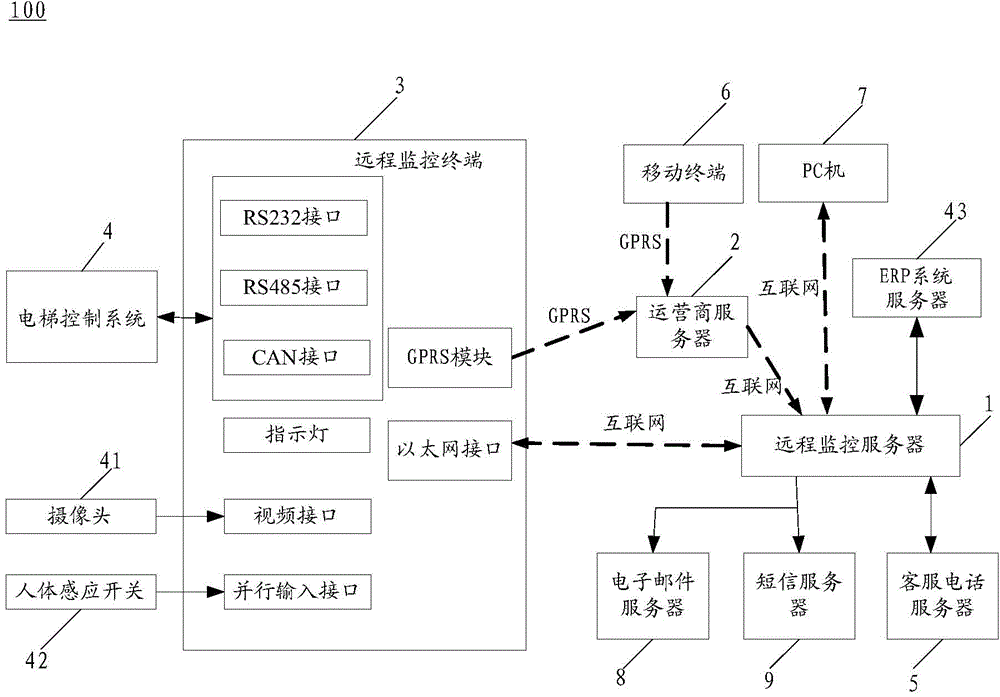
[0042] Please refer to figure 1 The elevator remote monitoring system 100 of the present invention includes a remote monitoring server 1, an operator server 2 (such as an operator data center server), a plurality of remote monitoring terminals 3 and a corresponding elevator control system 4, a customer service telephone server 5, and a mobile terminal 6 ( Such as mobile phone, ipad, etc.), PC 7, email server 8, short message server 9, camera 41, human body sensor switch 42 and ERP system server 43, wherein customer service telephone server 5, mobile terminal 6, PC 7, email server 8, short message server 9 and ERP system server 43 are all connected with remote monitoring server 1, camera 41 and human body sensor switch 42 are connected with remote monitoring terminal 3, each elevator control system 4 is connected with corresponding remote monitoring terminal 3, to collect corresponding The elevator data, the remote monitoring terminal 3 is connected to the operator server 2 and/or the remote monitoring server 1, the operator server 2 is connected to the remote monitoring server 1 through the Internet, and the remote monitoring terminal 3 wirelessly transmits the collected elevator data to the remote monitoring server 1, remote monitoring server 1 comprises receiving storage module 20 and alarm module 21, and receiving storage module 20 is used for receiving and storing the elevator data from each remote monitoring terminal 3, and alarm module 21 is connected with short message server 9 and email server 8, uses When the elevator data is the alarm information, the alarm message and the alarm mail are sent to the staff by the short message server 9 and the e-mail server 8 respectively. It should be noted, figure 1 Only one elevator is used as an example for illustration.
[0043] Compared with the prior art, the remote monitoring terminal 3 in the present invention collects elevator data in real time and uploads it to the remote monitoring server 1. When the elevator breaks down or there is a potential safety hazard, the remote monitoring server 1 can automatically judge as The corresponding elevator needs to call the police, so as to automatically send alarm text messages and alarm emails to the staff, so that the staff can immediately find elevator faults or potential safety hazards, and then deal with them in a timely manner, ensuring the safe operation of the elevator.
[0044] Wherein, the alarm information includes elevator failure alarm information, elevator failure emergency alarm information and elevator component life alarm information. Corresponding, such as figure 2 As shown, the alarm module 21 includes an elevator failure alarm unit 211 , an elevator failure emergency alarm unit 212 and an elevator component life alarm unit 213 . Elevator failure alarm unit 211 is used for when alarm information is elevator failure alarm information, sends by short message server 9 and e-mail server 8 respectively and comprises customer name, elevator ID, elevator failure title and failure code, failure handling method and failure time Alarm short message and alarm mail to the staff; Elevator failure trapped people's emergency alarm unit 212 is used for when the alarm information is the elevator failure trapped people's emergency alarm information, send by SMS server 9 and e-mail server 8 respectively and include customer name, elevator ID, Elevator fault name and fault code, fault handling method and the alarm text message and alarm mail of fault occurrence time to the staff; elevator component life alarm unit 213 is used for when the alarm information is the elevator component life alarm information, respectively through the short message server 9 and the electronic The mail server 8 sends an alarm text message and an alarm email containing the name of the part that has reached the predetermined service life to the staff. Thus the elevator remote monitoring system 100 of the present invention has three major alarm functions: an elevator failure alarm function, an elevator failure emergency alarm function, and an elevator component life alarm function. Each alarm function is described below: (1) Elevator failure alarm function: When an elevator fails, the elevator remote monitoring system will send the information of the elevator that has failed to the maintenance personnel and management personnel in a timely manner through text messages and emails. The elevator information includes: customer name, elevator number, elevator fault name and fault code, fault handling method, and fault time. (2) Elevator failure emergency alarm function: The elevator remote monitoring system judges that there is someone in the car through the camera in the elevator car or the human body sensor switch installed in the car, and then the elevator is in a fault state, meeting the signal condition "elevator fault + If there is someone in the car”, the remote monitoring system will send fault text messages and fault emails. Of course, at the same time, it can also automatically dial the phone number of the maintenance personnel or management personnel, and then voice broadcast the emergency fault of the elevator, and broadcast the customer’s name and elevator number. Elevator fault name and fault code, fault handling method, fault time. (3) Elevator component life alarm function: In the remote monitoring system, all the safety components of the elevator are listed. For each safety component, the operating times and operating life of the installed components can be set. The remote monitoring system counts each The operating times and age of safety components. When the safety components reach the set age, the system will automatically send the alarm information and alarm email of the parts that have reached the operating frequency and age to the maintenance personnel or management personnel, prompting timely maintenance and timely replacement, maintenance And after the replacement, the number of operations and the number of years can be set again.
[0045] In addition, the remote monitoring server 1 also includes a communication module 22 , a statistical module 23 , a statistical result display module 24 , an association module 25 , an automatic call module 26 , a login module 27 and a data connection module 28 .
[0046] Concretely, the communication module 22 is connected with the emergency alarm unit 212 for elevator failure and trapped people, and is used to automatically dial the staff's phone and voice broadcast the customer name, elevator ID, elevator failure when the alarm information is the elevator failure and trapped people's emergency alarm information. Name and fault code, fault handling method and fault occurrence time.
[0047] The statistics module 23 includes an elevator fault statistics unit 231 , an elevator maintenance data statistics unit 232 and an elevator passenger flow statistics unit 233 . Wherein, the elevator fault statistics unit 231 is connected with the receiving storage module 20, and is used for performing statistics on any relevant parameter of the elevator that has failed, and the relevant parameters include customer name, fault code, maintenance personnel, maintenance personnel check-in time, area Name, failure rate, repair time, elevator function code parameters, status of each terminal of the elevator, etc.; the elevator maintenance data statistics unit 232 is connected with the receiving storage module 20, and is used to make statistics on any relevant parameter of the elevator after maintenance; The passenger flow counting unit 233 is connected to the receiving storage module 20, and is used for counting the passenger flow of the elevator. It should be noted that the real-time uploaded elevator data includes elevator real-time data and elevator function code parameters. The elevator real-time data is the real-time changing data of the elevator operation, including the elevator's real-time floor, running status, door status, maintenance status, fault status, car board, car top board and the status of the input and output terminals of the main control board, etc.; through the elevator remote monitoring System 1 can observe real-time changes in elevator operation; elevator function code parameters are also updated in real time, as long as any parameter is changed or changed, this parameter will be uploaded to the server immediately and updated in time, and it is always consistent with the elevator data; each elevator The parameters of elevator function codes can be exported to Excel tables through mobile terminals, computers, etc. at any time. In addition, the elevator failure data and elevator maintenance data are stored on the remote monitoring server 1, and can be used for query and statistics; specifically, when the elevator fails, the remote monitoring server 1 immediately saves all the data of the elevator that has failed, including When a fault occurs, the real-time status of the real-time data of the elevator and the parameter value of the elevator function code, etc., and the saved elevator fault data and elevator maintenance data can be directly viewed or exported to an Excel data file, which is used to analyze the cause of the elevator fault and timely Provide accurate and feasible technical support to on-site maintenance personnel. By statistics module 23, elevator remote monitoring system 100 of the present invention has realized three major statistical functions: (1) statistics of elevator failure data: the data of the elevator of failure can be statistically analyzed according to different needs, and its statistical results are divided into: Customer name statistics, fault code statistics, maintenance personnel statistics, maintenance personnel check-in time statistics, area statistics, failure rate statistics, repair time statistics, etc.; in addition, the statistical results can be restricted according to the needs. The conditional restrictions include customer name, Fault code, maintenance personnel, check-in time of maintenance personnel, area name, failure rate, repair time, province, city, start time and end time, etc., and different condition restrictions can be selected according to different statistical result requirements. (2) Elevator maintenance data statistics: Statistical analysis can be performed on the elevator maintenance data according to different needs. The statistical results are divided into: customer name statistics, maintenance personnel statistics, maintenance personnel check-in time statistics, and regional statistics , maintenance rate statistics, maintenance time statistics, etc.; in addition, the statistical results can be restricted according to needs, such as customer name, maintenance personnel, check-in time of maintenance personnel, area name, maintenance rate, maintenance time , province, city, start time and end time, etc., and choose different conditional restrictions according to different statistical result requirements. (3) Elevator passenger flow statistics: Two methods of passenger flow data collection are used, and the two methods can be used selectively. The first method is digital image processing, that is, through the camera installed in the elevator, the image in the elevator is collected, and then through The digital image function designed by the elevator remote monitoring system 1 collects and analyzes the number and changes of the number of people in the elevator to count the flow of people, and then counts the flow of people in the elevator at each time period and on each floor, and can export it in an Excel form The statistical results can be used as a data analysis reference for elevator design; the second method is to use the light curtain signal to carry out elevator passenger flow statistics. When people take the elevator, there will be two actions, entering the elevator and exiting the elevator; the elevator remote monitoring system will activate the light curtain Count the number of times the elevator returns to the base station, divide the statistical value by two, and then count the passenger flow of the elevator in each time period and each floor, and export the statistical results in an Excel table, which can be used as an elevator design data analysis reference.
[0048] The statistical result display module 24 is connected with the statistical module 23, and is used to display the statistics of the elevator fault statistics unit 231, the elevator maintenance data statistics unit 232 and the elevator passenger flow statistics unit 233 in the form of statistical tables, pie charts, histograms or graphs. Statistical results; at the same time, the statistical results can also be exported in an Excel table, which can be used as a data analysis reference for elevator design.
[0049] The association module 25 is used to store the elevator ID, and is used to match the elevator data with the stored elevator ID when the remote monitoring terminal 3 uploads the elevator data, so as to realize automatic association identification between the elevator and the remote monitoring server 1 . Specifically, when the remote monitoring terminal 3 is installed on site, there is no need to make any settings for the remote monitoring terminal 3, just connect the basic line of the remote monitoring terminal 3, and the remote monitoring terminal 3 can automatically communicate with the remote monitoring server 1 according to the elevator ID. Realize association and accurately upload the data of each elevator. Among them, the elevator ID uniquely corresponds to an elevator, which uses a fixed function code parameter of the elevator. This function code parameter is only used as the elevator ID identification of the remote monitoring terminal. This function code parameter is set uniquely between each elevator; In the server 1, the corresponding elevator ID value is set for the content of each corresponding elevator, so that the replacement of any remote monitoring terminal 3 on the same elevator on site will not affect the automatic identification of elevator data.
[0050]Automatic call module 26 is connected with customer service telephone server 5 (specifically 400 customer service telephone systems), customer service telephone server 5 is used to receive the request telephone of customer or maintenance personnel and after receiving the request telephone, customer or maintenance personnel The information of the personnel is sent to the automatic call module 26, and the automatic call module 26 searches for the corresponding elevator according to the information of the customer or the maintenance personnel. Specifically, when a customer or a maintenance personnel etc. dial a call to the customer service personnel at the customer service telephone server 5, the customer service telephone server 5 sends the information of the customer or the maintenance personnel to the automatic call module 26 on the remote monitoring server 1, Then the remote monitoring server 1 automatically pops up the information of the customer or maintenance personnel who dialed the phone to the interface, and quickly indexes the elevators under the name of the customer and maintenance personnel, so as to quickly understand the needs of customers and maintenance personnel, and provide timely and reasonable services.
[0051] Login module 27, mobile terminal 6 and PC 7 are connected with login module 27, and are used for remote login remote monitoring server 1 to check elevator data in real time. Concretely, user or staff can log in remote monitoring server 1 by mobile terminal 6 (mobile phone, iPad etc.) or PC machine 7, because remote monitoring server 1 is the operation environment of the web page interface that adopts Web technology to make, B/S framework, And it is compatible with any browser login, so users can log in to the elevator remote monitoring system on mobile phones, iPads, computers and other places where browsers can be used, so as to realize remote monitoring of elevators anytime and anywhere.
[0052] In addition, the data docking module 28 is connected to the ERP system server 43, that is, the remote monitoring server 1 can perform data interaction with the ERP management system, realizing the functions of automatically adding and maintaining elevator basic information, and automatically compiling the elevator ID associated with the server. Usually, in the elevator remote monitoring system 100, if the remote monitoring function needs to be installed, the basic information of the elevator to be monitored must first be added to the remote monitoring server 1, and then the remote monitoring terminal is installed on the corresponding elevator. However, adding the basic information of the elevator on the remote monitoring server 1 is generally done manually, which is cumbersome and prone to errors. When the elevator manufacturer adopts the ERP management system, the ERP system already has the basic information of each elevator. Information, such as the customer name, control system, rated speed, rated load, floor, station, door, etc. of the elevator, so that for elevators that need to be installed with a remote monitoring function, the elevator remote monitoring system 100 is connected to the ERP system server 43 of the elevator manufacturer. It can automatically connect the basic information of the elevator, and automatically generate the elevator ID without manual filling, which is simple, fast and accurate.
[0053] Please refer to Figure 1 to Figure 14 , specifically describe a preferred embodiment of the remote monitoring terminal 3.
[0054] like figure 1 As shown, in the present embodiment, the remote monitoring terminal 3 includes an elevator data acquisition interface, a Zigbee interface, a video interface, a parallel input interface, a GPRS module, an Ethernet interface and an indicator light, wherein the elevator data acquisition interface specifically includes an RS232 interface, an RS485 interface and CAN interface. Specifically, the RS232 interface, the RS485 interface and the CAN interface are connected with the corresponding communication interface of the elevator control system 4 for collecting elevator data; the video interface is connected with the camera 41 for receiving image information in the elevator car collected by the camera; The input interface is connected with the human body induction switch 42, and the human body induction switch 42 is used to sense whether there is someone in the elevator car and the sensing result is transmitted to the remote monitoring terminal 3 through the parallel input interface; the GPRS module is connected with the operator's server 2 through the GPRS network, and uses To transmit the elevator data to the operator server 2, and then transmit the elevator data to the remote monitoring server 1 through the operator server 2; the Ethernet interface is connected to the remote monitoring server 1 through the Internet, and is used to transmit the elevator data to the remote monitoring server 1 ;Indicators include elevator fault indicator light, elevator inspection indicator light, power indicator light, and various network communication indicator lights, etc., which are used to indicate the status of the elevator or whether each circuit part is normal. The power indicator light is on when the power supply is normal, and the elevator The fault indicator light is on when the elevator fails, the elevator inspection indicator light is on when the elevator is in the inspection state, and various network communication indicators are on when the elevator data transmission network is normal.
[0055] Wherein, the elevator data acquisition interface in this embodiment includes two groups of above-mentioned CAN interfaces, wherein one group of CAN interfaces is connected with the corresponding elevator control system to collect corresponding elevator data, and the other group of CAN interfaces is connected with a plurality of remote monitoring terminals to receive Elevator data collected by multiple remote monitoring terminals. Thereby when there are multiple elevators in a certain community and a preset space range, the remote monitoring terminal 3 does not need to be provided with a GPRS module or an Ethernet interface for each, but only needs to install GPRS and/or Ethernet on one remote monitoring terminal 3 interface, and then realize the connection of multiple remote monitoring terminals 3 through the CAN bus interface, and other remote monitoring terminals 3 can transmit the corresponding elevator data collected to the remote monitoring terminal 3 installed with GPRS or Ethernet, and then through the remote monitoring terminal 3 The monitoring terminal 3 transmits the data of all elevators to the remote monitoring server 1, that is, realizes multi-function with two sets of CAN interfaces.
[0056] In addition, the connection between multiple remote monitoring terminals 3 is realized through the Zigbee interface. Thereby in the subdistrict, if a plurality of elevators and a plurality of remote monitoring terminals 3 are arranged in a certain range in the subdistrict, then a plurality of remote monitoring terminals 3 do not need each to be provided with a GPRS module or an Ethernet interface at this time, only one of them needs to be installed. A GPRS or Ethernet interface can be installed on one remote monitoring terminal 3; through Zigbee self-organizing network technology, other remote monitoring terminals 3 can transmit the corresponding elevator data collected to the remote monitoring terminal installed with GPRS or Ethernet 3. Then, the data of all elevators is transmitted to the remote monitoring server 1 through the remote monitoring terminal 3, which realizes multi-function in one belt.
[0057] It should be noted that the remote monitoring terminal 1 can only be equipped with a GPRS module or an Ethernet interface, as long as the data transmission can be realized through the wireless network. Of course, when the GPRS module and the Ethernet interface are included at the same time, the user can choose any One of the data transmission methods, if you choose GPRS network to transmit data, you only need to insert the data card into the data card slot, on the contrary, if you choose Ethernet (Internet) to transmit data, you only need to directly insert the normal network cable into the remote monitoring On the standard network interface on the terminal 3, the remote monitoring terminal 3 in the present invention is compatible with two network modes: GPRS and Ethernet, without changing the program.
[0058] Correspondingly, since the remote monitoring terminal 3 includes various interfaces, corresponding circuits need to be provided for each interface. Refer below Figure 3 to Figure 14 The corresponding circuit structure on the remote monitoring terminal 3 is specifically described.
[0059] like image 3 As shown, the remote monitoring terminal 3 includes a central control circuit 10 , a data input interface circuit 11 , a data output interface circuit 12 , a power supply circuit 13 and an indicator light circuit 14 . Wherein the data input interface circuit 11 comprises an RS232 interface circuit 111, an RS485 interface circuit 112, a CAN interface circuit 113, a parallel input interface circuit 114 and a Zigbee interface circuit 115; the data output interface circuit 12 comprises a GPRS module 121 and an Ethernet interface circuit 122. Wherein, RS232 interface circuit 111, RS485 interface circuit 112, CAN interface circuit 113, parallel input interface circuit 114 and Zigbee interface circuit 115 are connected with the input end of central control circuit 10, GPRS module 121 and Ethernet interface circuit 122 and central control circuit 10 output connections. The power supply circuit 13 is connected with the external 24V DC power supply and the central control circuit 10, the data input interface circuit 11, the data output interface circuit 12 and the indicator light circuit 14, and is used to convert the 24V DC power into 3.3V and 3.8V DC power for each circuit The module provides working power. The indicator light circuit 14 comprises a power indicator light unit 141, an elevator maintenance indicator light unit 142, an elevator failure indicator light unit 143, a data collection indicator light unit 144, a GPRS indicator light unit 145, an Ethernet indicator light unit 146 and a dry node input indicator light Unit 147. In addition, the remote monitoring terminal 3 also includes an SD card read-write circuit 15 .
[0060] Refer below Figures 4 to 14 Describe the connection relationship and working principle of each circuit module in detail.
[0061] like Figure 4 As shown, the power circuit 13 includes a protection unit 130, a first power conversion unit 131 and a second power conversion unit 132, and the protection unit 130 is connected to an external 24V DC power supply (DC24V) for reverse connection protection of the circuit; the first The power conversion unit 131 is connected with the protection unit 130, and is used to convert the 24V DC power supply into a DC3.8V power supply and provides the GPRS module 121 and the antenna; the second power conversion unit 132 is connected with the protection unit 130, and is used for converting the 24V DC power supply It is a DC3.3V power supply, which is provided to the central control circuit 10, data input interface circuit 11, data output interface circuit 12 and indicator light circuit 14. Specifically, the protection unit 130 includes a diode V1 and a fuse FUSE, one end of the diode V1 is connected to an external 24V DC power supply (DC24V), the other end is connected to one end of the fuse FUSE, and the other end of the fuse FUSE is connected to the first power conversion unit 131 and The second power conversion unit 132 is connected. The first power conversion unit 131 includes capacitors C1, C2, C3, a power conversion chip U1, an inductor L1, a resistor R1, a resistor R2, and a diode D1, wherein the power conversion chip U1 is specifically an LM2576-ADJ chip in this embodiment; the capacitor C1 One end of the capacitor C1 is connected to the other end of the fuse FUSE and pin 1 of the power conversion chip U1, the other end of the capacitor C1 is connected to pins 0, 3, and 5 of the power conversion chip U1 and grounded to GND, and pin 2 of the power conversion chip U1 It is connected with the cathode of the diode D1 and one end of the inductor L1, and the other end of the inductor L1 outputs a 3.8V DC power supply (VBAT3.8V, which is the output end of the first power conversion unit 131) and is connected with the capacitor C2, the capacitor C3, and the resistor R2. One end is connected, the other end of the resistor R2 is connected to the pin 4 of the power conversion chip U1 and one end of the resistor R1, the other end of the resistor R1, the other end of the capacitor C2 and the other end of the capacitor C3, and the anode of the diode D1 are grounded to GND, thus realizing the power supply The conversion chip U1 converts the external 24V DC power to 3.8V DC power. The second power conversion unit 132 includes capacitors C4, C5, C6, power conversion chip U2, inductor L2 and diode D2, wherein the power conversion chip U2 is specifically LM2576-3.3 in this embodiment; one end of the capacitor C4 is connected to the other end of the fuse FUSE One end is connected to pin 1 of the power conversion chip U2, the other end of the capacitor C4 is connected to pins 0, 3, and 5 of the power conversion chip U2 and grounded to GND, pin 2 of the power conversion chip U2 is connected to the cathode of the diode D2 and the inductor One end of L2 is connected, and the other end of inductor L2 outputs a 3.3V DC power supply (3.3V, which is the output end of the second power conversion unit 132) and is connected to capacitor C5, capacitor C6 and pin 4 of the power conversion chip U2, capacitor C5 And the other end of the capacitor C6 and the anode of the diode D2 are grounded to GND, so that the external 24V DC power can be converted into a 3.3V DC power through the power conversion chip U2.
[0062] like Figure 5As shown, the central control circuit 10 includes a single-chip microcomputer U3, an inductor L3, a resistor R16, a resistor R17, R42, an interface J4, J7, an interface J9, a clock circuit 101, a watchdog circuit 102, a backup power supply circuit 103, a power filter circuit 104 and Program test interface circuit 105, wherein the single-chip microcomputer U3 is specifically the STM32F107xx type microprocessor in this embodiment; one end of the inductance L3 is connected with the pin 22 of the single-chip microcomputer U3, and the other end is connected with the 3.3V power supply, and the pin 37 of the single-chip microcomputer U3 passes through the resistor R17 Grounding, the pin 94 of the microcontroller U3 is connected to the pin 2 of the interface J7, the pin 1 of the interface J7 is connected to the 3.3V power supply, the pin 3 of the interface J7 is grounded through the resistor R16, the pins 1 to 8 of the interface J9 are respectively connected to the pin 38 of the single chip U3 , 5, 4, 3, 2, 1, 98, 97 are connected, pins 9 to 16 of the interface J9 are grounded; pin 1 of the interface J4 is connected with pin 57 (S1) of the microcontroller U3, and pin 2 of the interface J4 is grounded through the resistor R42 . Specifically, the clock circuit 101 includes capacitors C11, C12, C13, C14, and crystal oscillators Y1, Y2; the capacitors C11, C12, and crystal oscillator Y1 are connected to form the main clock circuit, and are connected to the pins 8 and 9 of the single-chip microcomputer U3 to provide U3 provides the main clock signal; capacitors C13, C14 and crystal oscillator Y2 are connected to form an RTC clock circuit, and are connected to pins 12 and 13 of the single-chip microcomputer U3 to provide the RTC clock signal for the single-chip microcomputer U3. Watchdog circuit 102 includes chip U7 (in this embodiment, specifically MAX706 chip), resistors R73, R74, R75, R76, capacitor C62 and interface J11, the pin 1 of chip U7 is connected with pin 8, and the pin 2 of chip U7 is connected with pin 8. 3.3V power supply connection, pin 3 of chip U7 is grounded, pin 4 of chip U7 is grounded through resistor R73, pin 5 of chip U7 is suspended, pin 6 of chip U7 is grounded through resistor R74, pin 6 of chip U7 is connected to one end of resistor R75 , the other end of resistor R75 is connected to pin 1 of interface J11, pin 2 of interface J11 is connected to resistor R76, one end of capacitor C62 and pin 14 of single chip microcomputer U3 connection, the application of the watchdog circuit 102 enables the single-chip microcomputer U3 to realize continuous work in an unmanned state. Backup power supply circuit 103 comprises diode V2, diode V3, capacitor C57, capacitor C58 and battery BT1, the anode of diode V2 is connected with 3.3V power supply, the cathode of diode V2 is connected with pin 6 (Vb) of single-chip microcomputer U3, capacitor C57, capacitor C58 One end is connected to the cathode of the diode V3, the other end of the capacitor C57 and capacitor C58 is connected to the ground, the anode of the diode V3 is connected to the positive pole of the battery BT1, the negative pole of the battery BT1 is grounded, and the backup power supply circuit 103 is used to supply power to the backup area to maintain the single chip microcomputer U3 Save some data, including RTC/BKP registers, etc. The power filter circuit 104 includes capacitors C15 , C19 , C20 , C21 , and C18 connected in parallel. One end of each capacitor connected in parallel is connected to the 3.3V power generated by the power circuit 13 , and the other end is grounded. Program test interface circuit 105 is specifically JTAG test port in the present embodiment, comprises JTAG interface J3, resistance R88, R89, R90, R91 and R92, wherein pin 1 and pin 2 of JTAG interface J3 are connected with 3.3V power supply, JTAG interface Pin 3 (JNTRST) of J3 is connected with one end of resistor R88 and pin 90 of single-chip microcomputer U3, pin 5 (JTD1) of JTAG interface J3 is connected with one end of resistor R89 ​​and pin 77 of single-chip microcomputer U3, pin 7 of JTAG interface J3 (JTMS ) is connected with one end of resistor R90 and pin 72 of single-chip microcomputer U3, pin 13 (JTD0) of JTAG interface J3 is connected with one end of resistor R91 and pin 89 of single-chip microcomputer U3, and the other end of resistors R88, R89, R90, R91 is connected with 3.3V Power supply, pin 9 (JTCK) of JTAG interface J3 is connected to one end of resistor R92, the other end of resistor R92 is grounded, and pins 4, 6, 8, 10, 12, 14, 16, 18, 20 of JTAG interface J3 are grounded.
[0063] like Image 6 As shown, the RS232 interface circuit 111 includes a level shifting chip U4 (specifically the MAX232 chip in this embodiment), a socket RS1, a socket RS2, capacitors C27, C28, C29, C30, C31, resistors R18, R19, R20, R21, Zener diodes D3, D4, D5, D6 and components E12, E13, E14, E15. Among them, the pin 11 (ie U1TXPC) of the level conversion chip U4 is connected to the pin 2 of the interface J10, and the pin 14 of the level conversion chip MAX232 (ie RS232 TXD PC) is connected to the pin 2 of the socket RS1 through the resistor R18; the level conversion The pin 10 of the chip U4 (ie U2TX232) is connected to the pin 2 of the interface J8, the pin 7 of the level conversion chip MAX232 (ie RS232 TXD DT) is connected to the pin 2 of the socket RS2 through the resistor R21; the pin 8 of the level conversion chip U4 (i.e. RS232 RXD DT) is connected to pin 3 of socket RS2 through resistor R20, pin 12 of level conversion chip U4 (i.e. U1RX PC) is connected to pin 1 of interface J10; pin 13 of level conversion chip U4 (i.e. RS232 RXD PC) is connected to the pin 3 of the socket RS1 through the resistor R19, and the pin 9 (U2RX232) of the level conversion chip U4 is connected to the pin 1 of the interface J8; the pins 3 and 4 of the interface J8 are respectively connected to the pins 87 (U2RX), 86 (U2TX) connection; in addition, the element E12 is connected in parallel with the Zener diode D3 and one end of the parallel connection is grounded, the other end is connected with the pin 14 of the level conversion chip U4, and the element E13 is connected in parallel with the Zener diode D4 and one end of the parallel connection is grounded , the other end is connected to the pin 7 of the level conversion chip U4, the element E14 is connected in parallel with the Zener diode D5 and one end of the parallel connection is grounded, the other end is connected to the pin 8 of the level conversion chip U4, the element E15 is connected in parallel with the Zener diode D6 and One end of the parallel connection is grounded, and the other end is connected to pin 13 of the level conversion chip U4; pins 2 and 6 of the level conversion chip U4 are respectively grounded through capacitors C27 and C28, and pin 16 of the level conversion chip U4 is connected to a 3.3V power supply A capacitor C29 is connected between pin 1 and pin 3 of the level conversion chip U4, a capacitor C31 is connected between pin 4 and pin 5 of the level conversion chip U4, and pins 10 and 11 of the socket RS1 and RS2 are grounded.
[0064] like Figure 7 As shown, the RS485 interface circuit 112 includes an interface chip MAX485, a capacitor C32, resistors R22, R23, R24, R25, R26, Zener diodes D7, D8, components E19, E45, an interface J12, and interfaces J1 and J8, wherein the interface chip MAX485 The pin 6 of the resistor R22 and one end of the resistor R24, the cathode of the Zener diode D7, one end of the element E45 and one end of the resistor R25 are connected, the other end of the resistor R22 is connected to the 3.3V power supply, and the other end of the resistor R24 ​​is connected to the interface J12 Pin 1 is connected, the anode of Zener diode D7 and the other end of element E45 are grounded, the other end of resistor R25 is connected to pin 13 (ADATA+) of interface J1; pin 7 of the interface chip MAX485 is connected to one end of resistor R23, and the pin of interface J12 2. The cathode of Zener diode D8, one end of element E19 and one end of resistor R26 are connected, the other end of resistor R23 is grounded, the anode of Zener diode D8 and the other end of element E19 are grounded, the other end of resistor R26 is connected to the interface J1 Pin 14 (BDATA-) is connected; pin 1 (U2RX485) and pin 4 (U2TX485) of the interface chip MAX485 are respectively connected to pin 5 and pin 6 of the interface J8, and pin 2 and pin 3 (R/D) of the interface chip MAX485 are common Connect with the pin 85 of the single-chip microcomputer U3, the single-chip microcomputer U3 controls the sending and receiving of the interface chip MAX485, when the pin 85 output of the single-chip microcomputer U3 is low level, it is the receiving mode, when the pin 85 output of the single-chip microcomputer U3 is high level, it is the sending mode; in addition The pin 8 of the interface chip MAX485 is connected to the 3.3V power supply, and the capacitor C32 filters the power input to the interface chip MAX485.
[0065] As can be seen from the above, in this embodiment, the RS232 interface and the RS485 interface share the serial port 2 (USART2) of the single-chip microcomputer U3, and the RS232 and RS485 interface circuits respectively use MAX232 and MAX485 chips as the interface chips, and select RS232 or RS485 by jumpers.
[0066] like Figure 8 As shown, the CAN interface circuit 113 includes a first CAN interface unit 1131, a second CAN interface unit 1132, and an interface J2, wherein the first CAN interface unit 1131 includes a CAN chip U6, a capacitor C33, Zener diodes D9, D10, components E23, E24 and resistors R29, R30, R40, R41, the second CAN interface unit 1132 includes CAN chip U11, capacitor C35, Zener diodes D11, D12, elements E28, E29 and resistors R33, R34, R39. The circuit connection relationship of the first CAN interface unit 1131 is specifically described below: the pin 6 of the CAN chip U6 is connected to one end of the resistor R30, the other end (CAN1NL) of the resistor R30 is connected to the pin 2 of the interface J2, and the pin 7 of the CAN chip U6 is connected to the pin 2 of the interface J2. One end of the resistor R29 is connected, the other end of the resistor R29 (CAN1NH) is connected to one end of the resistor R40, the other end of the resistor R40 is connected to the pin 1 of the interface J2, the pin 6 of the interface J2 is grounded through the resistor R41, and the Zener diode D9 is connected to the component One end of E23 connected in parallel is grounded, and the other end is connected to pin 7 of CAN chip U6. One end of Zener diode D10 connected in parallel with component E24 is grounded, and the other end is connected to pin 6 of CAN chip U6. ), pin 4 (CAN1RX) are respectively connected with the pins 71 and 70 of the single-chip microcomputer U3; the pin 2 of the CAN chip U6 is grounded, the pin 3 of the CAN chip U6 is connected with the 3.3V power supply and one end of the capacitor C33, and the other end of the capacitor C33 is grounded, The pin 5 (S2) of the interface J2 is connected with the pin 84 of the single-chip microcomputer U3. The connection relationship of the components in the second CAN interface unit 1132 corresponds to the connection relationship of the components in the first CAN interface unit 1131 , and will not be described in detail here. It should be noted that the first CAN interface unit 1131 is used as a data acquisition interface for data acquisition of an elevator control system with a CAN communication protocol, and the second CAN interface unit 1132 is used as a multi-band interface for multiple elevators in the community. Just install GPRS or Ethernet on one elevator control device, and then connect multiple elevator control devices through the CAN bus interface, so that the data collected by other elevators can be transmitted to the control device installed with GPRS or Ethernet through the CAN interface, Furthermore, the data of all the elevators in the community can be sent back to the server through a device.
[0067] like Figure 9 As shown, the parallel input interface circuit 114 includes four photocouplers U12, resistors R8, R9, R10, R11, R12, R13, R14, R15 and interfaces J1, J13. The above components are connected into four parallel input interfaces. The following is a detailed description of one parallel input interface formed by photocoupler U12 and resistor R8: pin 1 of photocoupler U12 is connected to one end of resistor R15, and the other end of resistor R15 Connect with pin 2 of interface J13, pin 1 of interface J13 is connected with external 24V DC power supply, pin 3 of interface J13 is grounded, pin 15 of optocoupler U12 is grounded, pin 6 of optocoupler U12 is connected with one end of resistor R8 , the other end of the resistor R8 is connected to the 3.3V power supply, the pin 2 (X1) of the optocoupler U12 is connected to the pin 6 of the interface J1, and the pin 6 (XX1) of the optocoupler U12 is connected to the pin 63 of the microcontroller U3. , the optocoupler U12 conducts photoelectric isolation on the signal input from pin 2 (X1), and then outputs a level signal 0 or 1 from pin 6 (XX1) to the microcontroller U3. Similarly, the circuit connections and working principles of the other three parallel input interfaces are the same as above, and will not be described in detail here. The parallel input interface circuit 114 can be used for the detection of signals such as car passenger induction, and is reserved for other purposes, and its functions can be customized.
[0068] like Figure 10As shown, Zigbee interface circuit 115 comprises Zigbee interface chip J5, interface J10, light-emitting diode LED13, LED8, resistance R85, R87 and electric capacity C70, wherein the pin 14 (ZIG RST) of Zigbee interface chip J5 is connected with the pin 83 of single-chip microcomputer U3; Pins 11 (U1RX ZIGBEE) and 12 (U1TX ZIGBEE) of the Zigbee interface chip J5 are respectively connected to pins 5 and 6 of the interface J10; pin 7 of the Zigbee interface chip J5 is connected to the anode of the light-emitting diode LED13, and the cathode of the light-emitting diode LED13 is connected to the resistor One end of R87 is connected, the other end of resistor R87 is grounded; the pin 10 of Zigbee interface chip J5 is connected with the anode of light-emitting diode LED8, the cathode of light-emitting diode LED8 is connected with one end of resistor R85, and the other end of resistor R85 is grounded; Zigbee interface chip J5 The pin 9 of the connector is connected to the 3.3V power supply; the pins 3 (U1RX) and 4 (U1TX) of the interface J10 are respectively connected to the pins 69 and 68 of the single-chip microcomputer U3.
[0069] Depend on Figure 6 to Figure 10 It can be seen that the remote monitoring terminal 3 in the elevator remote monitoring system 100 of the present invention is provided with various serial input interfaces (such as RS232, RS485 and CAN bus interface) and parallel input interfaces as data acquisition interfaces. According to different communication protocols, users can freely choose RS232, RS485 or CAN interface to collect data, only need simple setting, and the applicable scope is wider. At the same time, the multi-channel parallel input port uses a bidirectional optocoupler to perform photoelectric isolation of the signal, and outputs a level signal of 0 or 1 to the microcontroller U3. The parallel input port can be used for the detection of signals such as car passenger induction, and is reserved for other purposes. Functions can be customized so that more functions can be extended.
[0070] The following describes the data output interface circuit 12 respectively:
[0071] like Figure 11 As shown, the GPRS module 121 includes a SIM card holder U9, a GPRS chip U8, capacitors C44, C45, C46, ​​C47, C48, C49, C50, C51, C52, C53, C54, C55, C56, C60, resistors R82, transistor Q2 , transistor Q3, transistor Q4, resistors R78, R79, R80, R81, R82, R86, components E38, E39, E40, E41, light emitting diode LED7 and interface P2. Among them, capacitors C48, C49, C50, C51, C52, C53, C54, and C55 are connected in parallel to form a filter circuit. One end of the filter circuit is connected to VBAT3.8V power supply and pin 26 and pin 27 of GPRS chip U8, and the other end is connected to GPRS chip Pins 1, 21, 22, 24, 25, 28, and 46 of U8 are commonly grounded to GND, pin 8 of GPRS chip U8 is connected to VBAT3.8V power supply and one end of capacitor C56 and capacitor C60, and the other end of capacitor C56 and capacitor C60 is grounded , the pins 7 and 10 of the GPRS chip U8 are respectively connected to the collectors of the triode Q2 and the triode Q3, the base of the triode Q2 is connected to the pin 54 (RST GPRS CTL) of the microcontroller U3 through the resistor R83, and the base of the triode Q3 is connected through the resistor R78 Connect with the pin 53 (PWR GPRS CTL) of the single-chip microcomputer U3, the emitters of the triode Q2 and the triode Q3 are grounded, and the pins 45 and 44 of the GPRS chip U8 are connected with the pins 56 (U3RX) and 55 (U3TX) of the single-chip microcomputer U3 through the resistors R81 and R80 respectively. ), the pin 39 of the GPRS chip U8 is connected to the base of the transistor Q4 through the resistor R79, the emitter of the transistor Q4 is connected to the cathode of the light-emitting diode LED7, the anode of the light-emitting diode LED7 is connected to the VBAT3.8V power supply, and the collector of the transistor Q4 Grounding, the pin 23 of the GPRS chip U8 is connected to the pin 1 of the interface P2, the pin 2 of the interface P2 is grounded, the pin 49 of the GPRS chip U8 is connected to the GPRS indicator unit; one end of the parallel connection of the capacitor C44 and the component E41 is grounded, and the other end is connected to the ground. The pin 6 (SIM DATA) of SIM card holder U9 is connected, one end of capacitor C45 connected in parallel with element E40 is grounded, the other end is connected with pin 3 (SIM CLK) of SIM card holder U9, and the end of capacitor C46 connected in parallel with element E39 is grounded , the other end is connected to pin 2 (SIM RST) of SIM card holder U9, one end of capacitor C47 connected in parallel with component E38 is grounded, the other end is connected to pin 1 (SIM VCC) of SIM card holder U9, and the pin of SIM card holder U9 4 is grounded; at the same time, the pins 1, 2, 3, and 6 of the SIM card holder U9 are respectively connected to the pins 2, 6, 5, and 4 of the GPRS chip U8. During work, single-chip microcomputer U3 is connected with GPRS module 121 through serial port 3 (being pin U3TX and pin U3RX), sends data to GPRS module 121, and GPRS module 121 is transmitted to Internet by GPRS network, is transmitted to server at last.
[0072] like Figure 12 As shown, the Ethernet interface circuit 122 includes an Ethernet chip U10 (specifically, a DP83848 chip in this embodiment), resistors R59, R60, R61, R62, R63, R64, R65, R66, R69, R70, R71, R72, capacitors C37, C38, C39, C40, C41, C42, C43, interface CN1 (in this embodiment, it can be HR911105A chip). Pin 1 and pin 2 of the Ethernet chip U10 are respectively connected to pin 18 and pin 48 of the single-chip microcomputer U3 through resistors R43 and R44, and pins 3 to 6 of the Ethernet chip U10 are respectively connected to the single-chip microcomputer through resistors R45, R46, R47, and R48. Pins 95, 17, 52, and 51 of U3 are connected, pins 40 and 42 of the Ethernet chip U10 are connected to pins 23 and 26 of the single-chip microcomputer U3 through resistors R49 and R50 respectively, and pin 38 of the Ethernet chip U10 is connected to the single-chip microcomputer U3 through resistor R51 Pin 24 of the Ethernet chip U10 is connected to pin 43 to pin 46 of the Ethernet chip U10 respectively through resistors R55, R54, R53, R52 and pins 33, 34, 35, 36 of the microcontroller U3, and pins 39 and 41 of the Ethernet chip U10 are respectively connected to Resistors R56 and R57 are connected to pins 32 and 47 of the single-chip microcomputer U3, pin 31 of the Ethernet chip U10 is connected to pin 16 of the single-chip microcomputer U3, pin 30 of the Ethernet chip U10 is connected to the resistor R59 and one end of the resistor R58, and the other end of the resistor R59 One end is connected to the 3.3V power supply, the other end of the resistor R58 is connected to the pin 25 of the single-chip microcomputer U3, the pin 29 of the Ethernet chip U10 is connected to the pin 61 of the single-chip microcomputer U3, and the pin 7 of the Ethernet chip U10 is connected to the resistor R60 and one end of the resistor R , the other end of the resistor R60 is connected to the 3.3V power supply, the other end of the resistor R is connected to the pin 31 of the single-chip microcomputer U3; the pin 34 (MCO) of the Ethernet chip U10 is connected to the pin 67 of the single-chip microcomputer U3, and the pin 24 of the Ethernet chip U10 Ground through resistor R61, one end of capacitors C37, C38, C39, and C40 connected in parallel is connected to pins 18, 23, and 37 of the Ethernet chip U10, and the other end is grounded, and pins 15, 19, 35, 47, and 36 of the Ethernet chip U10 Grounding, the pins 22, 32, 48 of the Ethernet chip U10 are connected to the 3.3V power supply, the pins 20, 21 of the Ethernet chip U10 are respectively connected to the 3.3V power supply through the resistors R62, R63, and the pins 26, 27, 28 are connected to the 3.3V power supply through resistors R64, R65, and R66 respectively, and pins 13 (RD-), 14 (RD+), 16 (TD-), and 17 (TD+) of the Ethernet chip U10 are connected to the 3.3V power supply through resistors R72, R71, and R70 respectively. , R69 is connected to the pins 6, 3, 2, 1 of the interface CN1, and the pins 4 and 5 of the interface CN1 are connected to the 3.3V power supply. Among them, the capacitors C41, C42, and C43 are connected in parallel to form a filter circuit for the 3.3V power supply. filtering. When working, the single-chip microcomputer U3 transmits the data to the Internet through the Ethernet interface circuit 122, and finally transmits the data to the server.
[0073] It should be noted that in the present invention, data input with multi-function can be realized by the wireless transmission of the ZigBee interface circuit 115 in addition to being realized by the CAN interface circuit 113. The transmission mechanism of the ZigBee wireless transmission is consistent with the mechanism of the CAN communication, and will not be repeated here. Detailed Description.
[0074] In addition, the remote monitoring terminal 3 also includes an SD card read-write circuit 15, the SD card communicates with the single-chip microcomputer U3 through the SPI mode, and the single-chip microcomputer U3 reads and writes the data in the SD through the bus SPI communication mode. Specifically, such as Figure 13 Shown, SD card read-write circuit 15 comprises SD card socket SD1, resistance R35, R36, R37, R38 and element E31, E32, E34, E35, wherein the pin 2 (SPI13 NSS) of SD card socket SD1 and the pin of single-chip microcomputer U3 29 and element E31, one end of resistor R38 is connected, the other end of element E31 is grounded, the other end of resistor R38 is connected to 3.3V power supply, pin 3 (SPI13 MOSI) of SD card socket SD1 is connected to pin 80 of single-chip microcomputer U3 and element E32, One end of the resistor R37 is connected, the other end of the element E32 is grounded, the other end of the resistor R37 is connected to the 3.3V power supply, the pin 4 of the SD card socket SD1 is connected to the 3.3V power supply, and the pin 5 (SPI13 SCK) of the SD card socket SD1 is connected to the microcontroller Pin 78 of U3 is connected with element E34 and one end of resistor R36, the other end of element E34 is grounded, the other end of resistor R36 is connected with 3.3V power supply, pin 6 of SD card socket SD1 is grounded, pin 7 of SD card socket SD1 (SPI13 MISO) is connected with the pin 79 of the single-chip microcomputer U3 and one end of the element E35 and the resistor R35, the other end of the element E35 is grounded, and the other end of the resistor R35 is connected with the 3.3V power supply.
[0075] like Figure 4 to Figure 14 As shown, the indicator light circuit 14 includes a power indicator light unit 141, an elevator maintenance indicator light unit 142, an elevator fault indicator light unit 143, a data collection indicator light unit 144, a GPRS indicator light unit 145, an Ethernet indicator light unit 146 and a dry node Enter the indicator light unit 147 . Specifically, such as Figure 14As shown, the power indicator unit 141 includes a light emitting diode LED1, a resistor R3, a light emitting diode LED6 and a resistor R4. The anode of the light emitting diode LED1 is connected to the output terminal (3.3V) of the second power conversion unit 132, and the cathode of the light emitting diode LED1 is connected to the output terminal (3.3V) of the second power conversion unit 132. One end of the resistor R3 is connected, and the other end of the resistor R3 is grounded; the anode of the light emitting diode LED6 is connected to the output terminal (VBAT3.8V) of the first power conversion unit 131, the cathode of the light emitting diode LED6 is connected to one end of the resistor R4, and the resistor R4 The other end is grounded; thus when the two power supplies (3.3V and 3.8V) are normal, both indicator lights are on, and any one light is off, indicating that the power supply is abnormal. Elevator maintenance indicator unit 142 comprises light-emitting diode LED3 and resistance R5, and the anode of light-emitting diode LED3 is connected with the output end (3.3V) of second power conversion unit 132, and the negative electrode of light-emitting diode LED3 is connected with one end of resistance R5, and resistance R5 is another One end is grounded, when the elevator is in the state of inspection, the indicator light (light-emitting diode LED3) is on, otherwise it is off. Elevator fault indicator unit 143 comprises light-emitting diode LED4 and resistance R6, and the anode of light-emitting diode LED4 is connected with the output terminal (3.3V) of second power conversion unit 132, and the negative electrode of light-emitting diode LED4 is connected with one end of resistance R6, and resistance R4 is another One end is grounded, when the elevator is in failure, the indicator light (light-emitting diode LED4) is on, otherwise it is off. The data acquisition indicator unit 144 includes a light-emitting diode LED2 and a resistor R7, the anode of the light-emitting diode LED2 is connected to the output terminal (3.3V) of the second power conversion unit 132, the cathode of the light-emitting diode LED2 is connected to one end of the resistor R7, and the resistor R7 is connected to another end of the resistor R7. One end is grounded, when the data acquisition is normal, the indicator light (light-emitting diode LED2) is on, otherwise it is off. GPRS indicator unit 145 comprises light-emitting diode LED5, resistance R84, resistance R83 and triode Q1, and the anode of light-emitting diode LED5 is connected with the output end (3.8V) of first power conversion unit 131, and the cathode of light-emitting diode LED5 is connected with one end of resistance R84 connection, the other end of the resistor R84 is connected to the emitter of the transistor Q1, the base of the transistor Q1 is connected to the GPRS module 121 through the resistor R83, and the collector of the transistor Q1 is grounded, so that when the GPRS module 121 communicates normally, the indicator light (light emitting diode LED5) is turned on and off once every 75ms. When the communication of the GPRS module 121 is abnormal, the indicator light is turned on and off for 75ms and turned off for 3s. The Ethernet indicator unit 146 includes a resistor R67, a resistor R68 and two light emitting diodes ( Figure 10 Not shown in ), wherein the two light-emitting diodes are yellow and green light-emitting diodes, one end of the resistor R67 and the resistor R68 are respectively connected to the anodes of the two light-emitting diodes, and the cathodes of the two light-emitting diodes are respectively connected to pins 9 and 9 of the interface CN1. Pin 12 is connected, and the other end of resistor R67 and resistor R68 is connected to the 3.3V power supply. When the Ethernet data transmission is normal, the yellow and green indicator lights flash alternately, otherwise they are off. The dry node input indicator unit 147 includes light emitting diodes LED9, LED10, LED11 and LED12, the dry node input indicator unit 147 is connected to the parallel input interface circuit 114, and the four light emitting diodes are respectively connected to four parallel input ports. Specifically, The anode of the light emitting diode LED9 is connected to the 3.3V power supply, the cathode of the light emitting diode LED9 is connected to the other end of the resistor R8, the connection relationship of other light emitting diodes is the same, and will not be described in detail here.
[0076] The present invention has been described above in conjunction with the best embodiments, but the present invention is not limited to the above-disclosed embodiments, but should cover various modifications and equivalent combinations made according to the essence of the present invention.

PUM

no PUM

Description & Claims & Application Information

We can also present the details of the Description, Claims and Application information to help users get a comprehensive understanding of the technical details of the patent, such as background art, summary of invention, brief description of drawings, description of embodiments, and other original content. On the other hand, users can also determine the specific scope of protection of the technology through the list of claims; as well as understand the changes in the life cycle of the technology with the presentation of the patent timeline. Login to view more.

Similar technology patents

Method for searching heavy metal hyper accumulator

Owner:SOUTH CHINA BOTANICAL GARDEN CHINESE ACADEMY OF SCI

Classification and recommendation of technical efficacy words

  • Easy to find
  • Guaranteed safe operation

System and method for directory services and e-commerce across multi-provider networks

InactiveUS7340048B2Easy to identifyEasy to findTelephone data network interconnectionsAccounting/billing servicesNetwork providersWeb system
Owner:WALMART APOLLO LLC

Interactive television system with newsgroups

InactiveUS20100115559A1Easy to findTelevision system detailsMultimedia data queryingInteractive televisionApplication software
Owner:ROVI GUIDES INC

Fiber monitoring system

InactiveCN103647601AAccurately determine the location of the faultGuaranteed safe operationFibre transmissionVIT signalsControl bus
Owner:STATE GRID CORP OF CHINA +2

Anomalous video warning device for ATM

InactiveCN101609581APrevention and reduction of illegal activitiesGuaranteed safe operationComplete banking machinesBurglar alarmEvent analysisReal-time computing
Owner:YUNNAN ZHENGZHUO INFORMATION TECH
Why Eureka
Try Eureka