
An oblique stripe mosaic imaging method for narrow and long target areas of remote sensing satellites

A technology for target areas and remote sensing satellites, applied in the field of remote sensing, it can solve the problems of complex imaging process and not yet found to cover narrow and long target areas, and achieve the effect of simplifying calculation problems, improving satellite imaging efficiency, and simplifying width changes.

Active Publication Date: 2017-04-19
AEROSPACE DONGFANGHONG SATELLITE
View PDF1 Cites 0 Cited by
  • Summary
  • Abstract
  • Description
  • Claims
  • Application Information

AI Technical Summary

Problems solved by technology

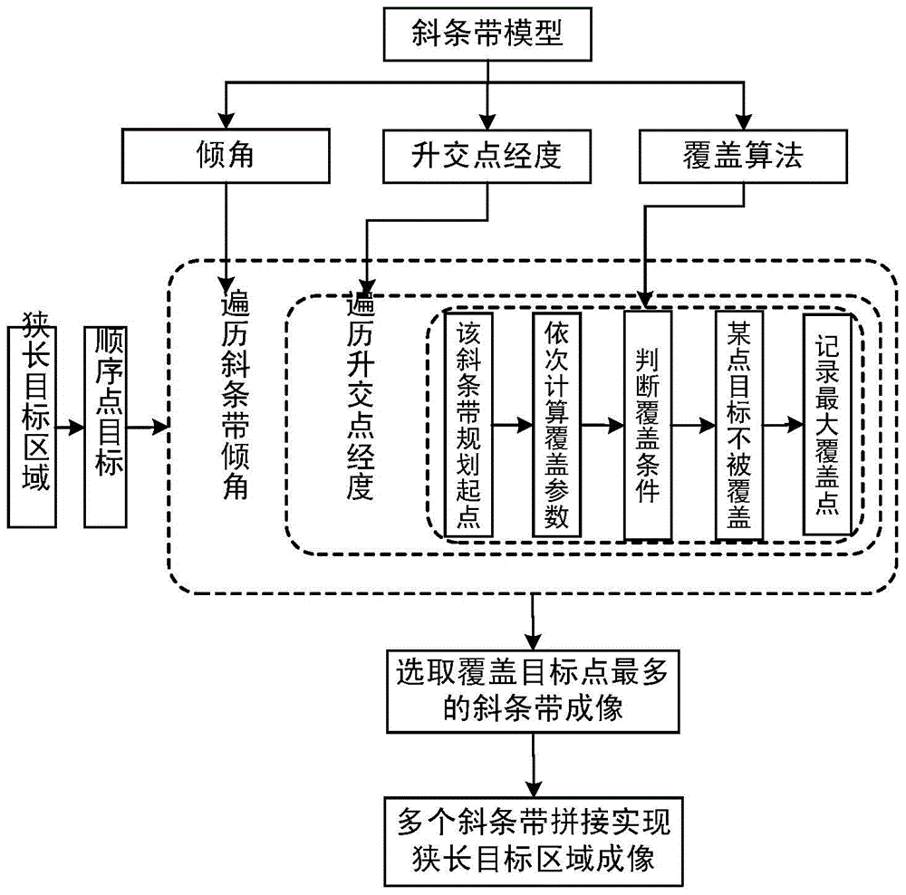
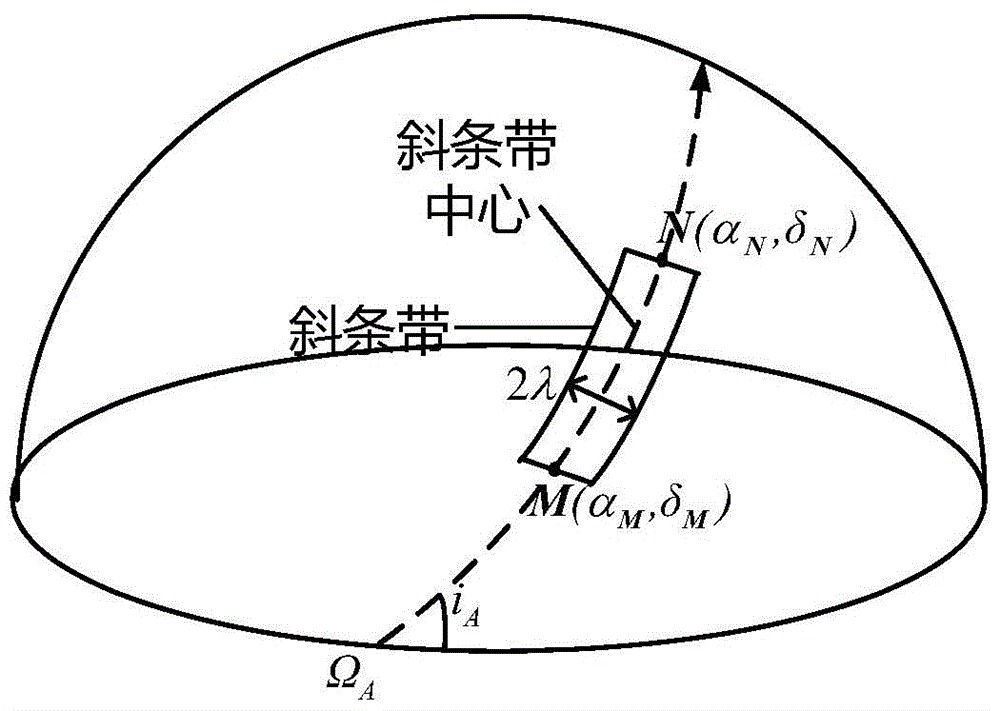
[0004] According to the characteristics of imaging in attitude maneuvering, it can realize diagonal strip imaging, that is, strip imaging with a certain angle between the imaging strip and the sub-satellite point track, and the splicing of these diagonal strips in different directions can realize the long and narrow target The complete coverage imaging of the area, but the whole imaging process is relatively complicated, involving the basic model of the oblique strip, the simplification of the narrow and long target area, and the principle of parameter selection of the imaging strip, etc.
At present, there is no research or report on the use of oblique strip splicing to cover narrow and long target areas

Method used


Image

  • An oblique stripe mosaic imaging method for narrow and long target areas of remote sensing satellites
  • An oblique stripe mosaic imaging method for narrow and long target areas of remote sensing satellites
  • An oblique stripe mosaic imaging method for narrow and long target areas of remote sensing satellites

Examples


Embodiment

[0050] Taking the east coast of China as an example, the following describes the imaging method of covering the narrow and long target trajectory by splicing oblique strips:

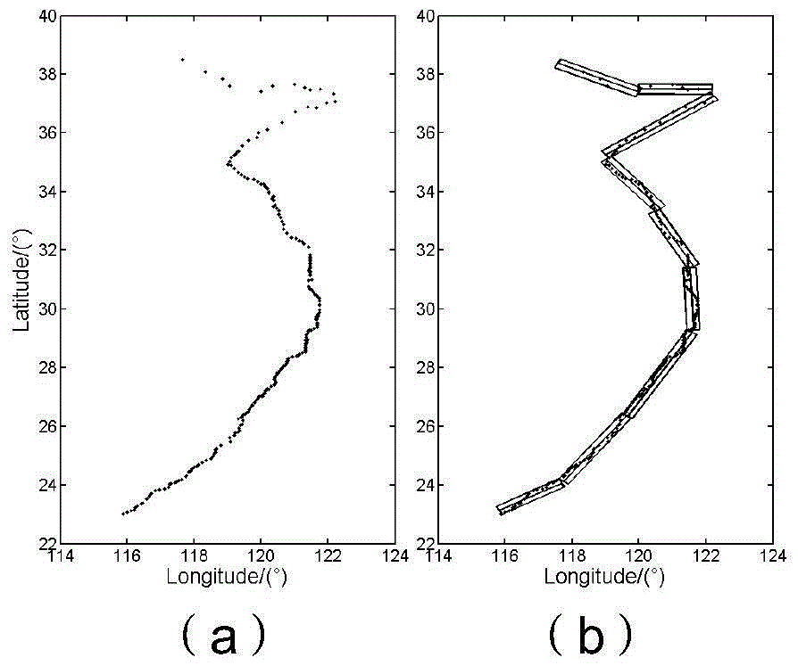
[0051] Take the eastern coastline of China, which is about 2500km long from latitude and longitude (117.66°, 38.51°) to (115.89°, 23.02°) from north to south, the east coastline of China is long and irregular in shape, so it is difficult to use strips in the same direction. To achieve coverage imaging with multiple oblique strips, splicing is required. It is first reduced to a sequence of point targets, such as Image 6 As shown in a, it is simplified to 216 point targets in total. In actual use, some key areas are replaced with dense point targets to ensure absolute coverage of the key areas. The oblique strip splicing imaging method of the present invention is used to continuously splice it imaging. The observation width of the satellite is 2λ=30km, the calculation takes the inclination step di=0.1°,...


PUM


Abstract

The invention discloses an inclined strip splicing imaging method of a narrow and long object area of a remote sensing satellite, and brings forward a method for continuous and complete coverage imaging of a narrow and long object area by use of inclined strips in different directions, for overcoming the problem of difficult effective imaging of the narrow and long object area since an imaging area has to be parallel to a subtrack by use of a conventional imaging mode. The method comprises: first of all, simplifying the narrow and long object area to be sequentially arranged point objects so as to realize conversion into a problem of sequential coverage imaging of the point objects; then obtaining an optimal inclined strip through detailed explanation of a method for selecting the inclined strips capable of imaging a largest number of the object points; and finally, splicing the inclined strips in the different directions so as to realize continuous and complete imaging of the narrow and long object area. According to the invention, the problem of simplifying the narrow and long object area is solved, the method for effective splicing imaging of the locus of the narrow and long object area by use of the inclined strips is brought forward, and continuous and complete imaging of such narrow and long object areas as a road, a coastline and the like during satellite attitude maneuvering can be realized.

Description

technical field [0001] The invention belongs to the field of remote sensing and relates to a method for imaging a long and narrow target area by a remote sensing satellite. Background technique [0002] At present, when remote sensing satellites image the ground, the imaging area is mainly a rectangular area, and the imaging strip parallel to the sub-satellite point track and the same flying direction as the satellite is usually used to image the rectangular area. However, for some tasks with special imaging requirements, such as imaging of targets in long and narrow areas along roads, rivers, coastlines, and borders, it is difficult to use one or multiple strips in the same direction due to the irregular shape of the target area To achieve coverage, or use the same direction of strip coverage is relatively low efficiency, for example, to complete the coverage of the eastern coastline of China, if the number of strips required to cover a single direction of strip splicing is...

Claims


Application Information

Patent Timeline
Patent Type & Authority Patents(China)
IPC IPC(8): G06T3/40G06T5/50
CPCG06T3/4038G06T5/50
Inventor 黄敏杨芳葛玉君黄群东
Owner AEROSPACE DONGFANGHONG SATELLITE
Learn More