Array mechanism of laser spot projector with adjustable light spot density

A density and laser technology, applied in the direction of instruments, measuring instruments, active optical measuring devices, etc., can solve the problem that the feature points cannot be extracted, and achieve the effect of solving the problem that cannot be extracted

Active Publication Date: 2015-02-11
BEIJING AEROSPACE INST FOR METROLOGY & MEASUREMENT TECH +1
View PDF4 Cites 4 Cited by
  • Summary
  • Abstract
  • Description
  • Claims
  • Application Information

AI Technical Summary

Problems solved by technology

[0004] The purpose of the present invention is to provide a laser point thrower array mechanism with adjustable density of light spots, which can adjust the density of light spots and solve the problem that feature points cannot be extracted under bright background

Method used


Image

  • Array mechanism of laser spot projector with adjustable light spot density
  • Array mechanism of laser spot projector with adjustable light spot density
  • Array mechanism of laser spot projector with adjustable light spot density

Examples


Embodiment Construction

[0021] The present invention will be described in further detail below in conjunction with the accompanying drawings and specific embodiments.

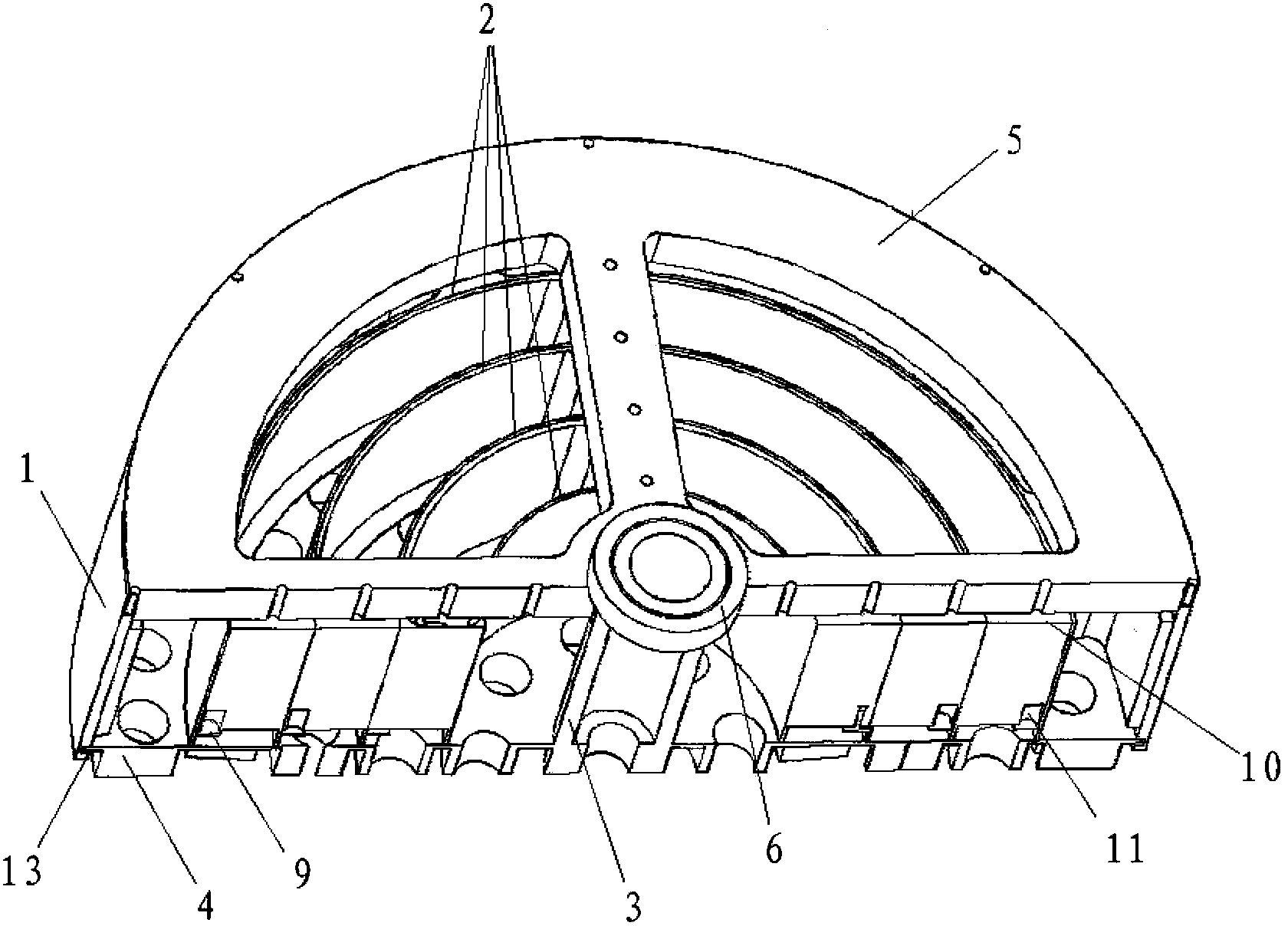
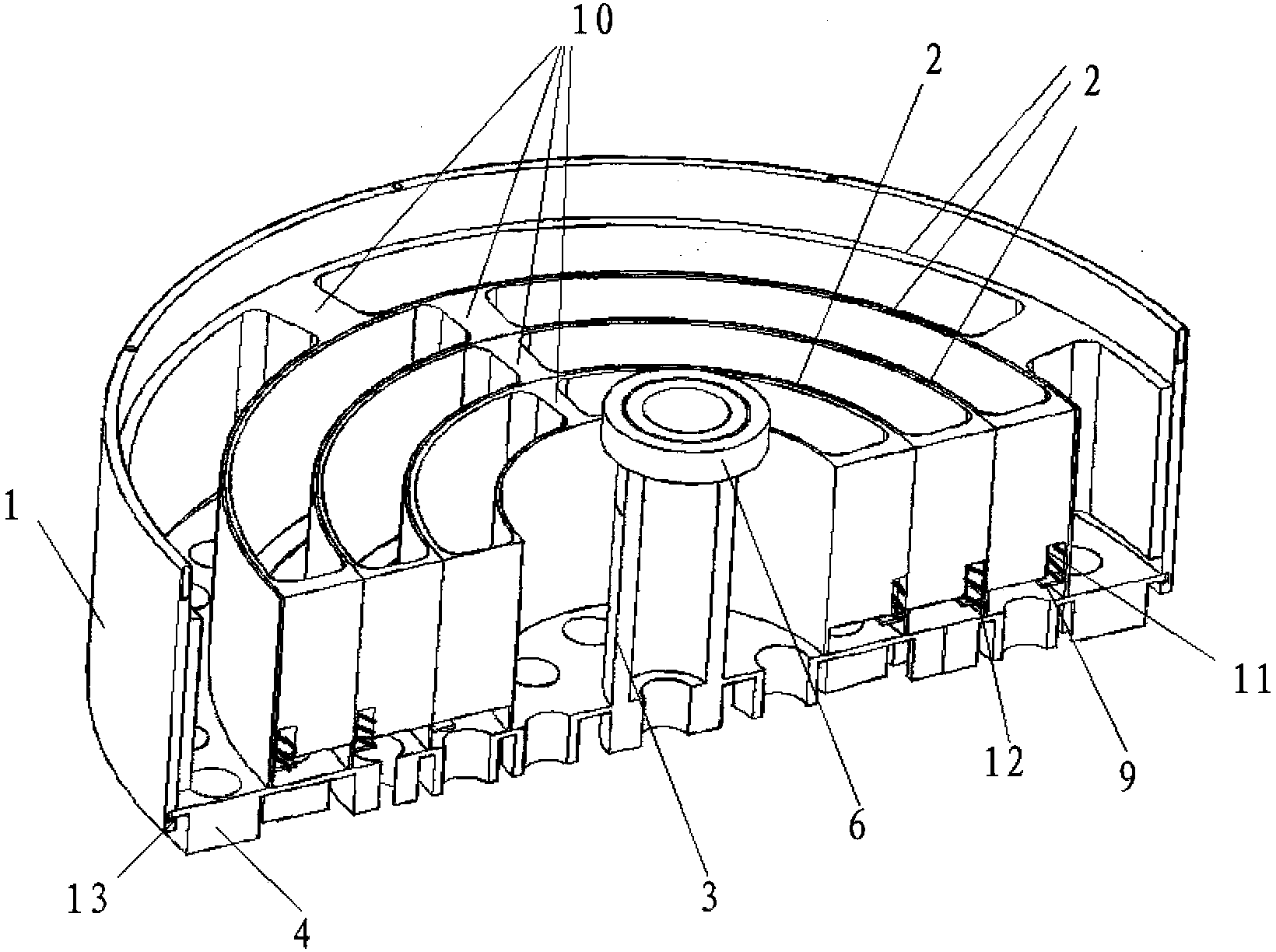
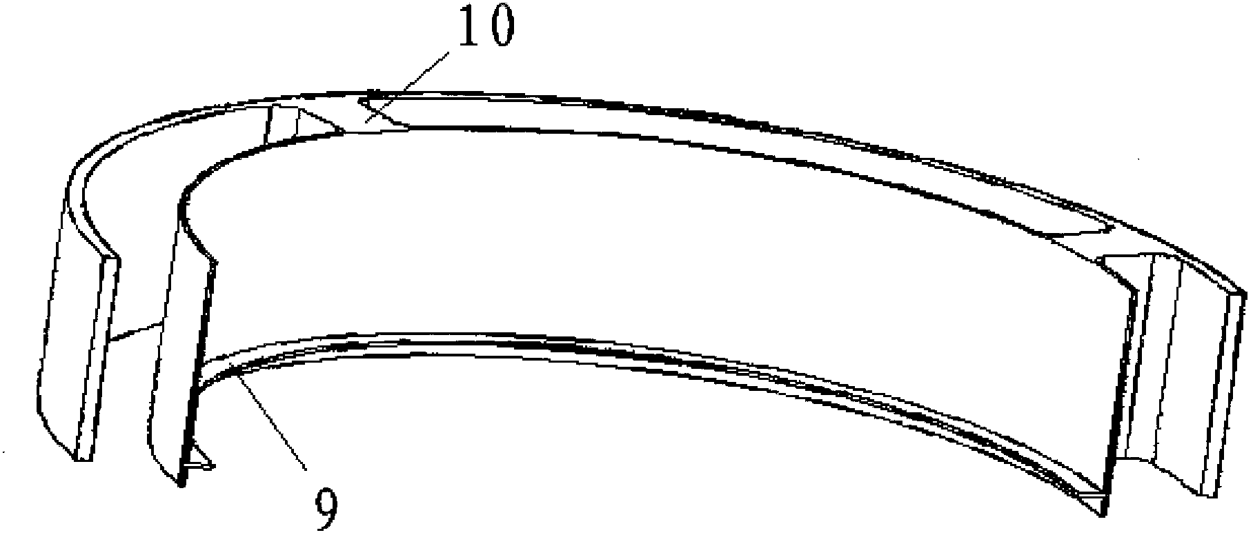
[0022] Such as Figure 1 ~ Figure 4 As shown, the front end of the cylindrical base 1 is fixedly installed with a front end cover 5 through threads, and the rear end cover 4 is fixedly installed at the rear end. An auxiliary support ring 2 is installed in the cylinder base 1 .

[0023] Such as figure 1 with Figure 4 As shown, the rear end cover 4 is circular, and several circular array blocks 7 are integrally processed on the outer end surface, and the circular array blocks 7 are arranged in circles on the rear end cover 4 to form an annular array. The ring array block 7 forms each circle, and an annular groove 14 is formed between adjacent circles. In the center of the rear end cover 4, a force application rod 3 is integrally processed. One end of the force application rod 3 is circular, and a laser fixing hole 8 is processed in...


PUM


Abstract

The invention belongs to the engineering measurement technology and specifically discloses an array mechanism of a laser spot projector with an adjustable light spot density. The array mechanism comprises a cylindrical base, a rear end cover, a front end cover, a force applying rod and an auxiliary supporting ring. Circular-ring array blocks which are arranged into circles around the center of the rear end cover are arranged on the outer end surface of the rear end cover; a ring-shaped slot is formed between adjacent circular rings; a laser device fixing hole is formed in the center of the circular-ring array blocks. The circular-ring array blocks which are arranged into circles are designed on the rear end cover made of an elastic material, and the ring-shaped slots are formed among the circles, so that elastic deformation formed by the ring-shaped slots is generated between the circular-ring arrays when the force applying rod drives the rear end cover to move, and a normal of each circular hole generates deflection for a certain angle, thereby generating or converging or diverging a laser spot matrix on the target to generate a laser spot array adaptive to a target dimension size, and solving a problem that characteristic spots cannot be extracted under a high-brightness background.

Description

technical field [0001] The invention belongs to engineering measurement technology, and in particular relates to an elastic adjustment device for adjusting the photoelectric density distance of a laser point thrower array. Background technique [0002] In the field of machine vision and photogrammetry, feature marker points are often used as measurement points. There are many ways to generate characteristic mark points, such as sticking directional reflective marks on the measured target, fixing active luminous marks on the measured target, projecting laser points on the measured target, etc. In some specific occasions (such as high-temperature targets, glass surfaces, and mesh surfaces), fixed marker points cannot be pasted, and the characteristic marker points can only be generated by projecting laser points. Therefore, the laser dot thrower has a wider application as a non-contact feature marker point generator. [0003] At present, the main principle of the laser spott...

Claims


Application Information

Patent Timeline
Patent Type & Authority Applications(China)
IPC IPC(8): G01C15/00
CPCG01C15/002
Inventor 宋金城梁雅军刘柯孙增玉
Owner BEIJING AEROSPACE INST FOR METROLOGY & MEASUREMENT TECH
Why Eureka
Try Eureka