Footstand adjusting and positioning structure of magnifying lens device

A technology of positioning structure and magnifying glass, applied in magnifying glass, optics, instruments and other directions, can solve the problems of breakage and damage of the clamping block 251, easy shaking of the foot seat 24, and shortening of service life, etc., to achieve the effect of improving the convenience of use.

Inactive Publication Date: 2015-02-11
GEM OPTICAL
View PDF4 Cites 1 Cited by
  • Summary
  • Abstract
  • Description
  • Claims
  • Application Information

AI Technical Summary

Problems solved by technology

[0004] It utilizes the clamping block 251 of the rod 25 to be engaged between any two locking teeth 242 of the foot base 24 to adjust the relative pivot position between the base 24 and the grip body 21. However, the clamping block 251 of the rod 25 It can only be engaged between any two locking teeth 242 of the foot seat 24 in a segmented manner, so that the adjustment of the foot seat 24 is restricted from pivoting, thereby causing inconvenience in use
[0005] It utilizes the positioning method that the clamping block 251 of the rod 25 and the two locking teeth 242 of the foot base 24 are engaged with each other, so that the base 24 is pivotally folded or unfolded. There is often a gap between the two locking teeth 242 of 24. This gap not only cannot accurately position the foot 24, but also makes the foot 24 easy to shake, which causes troubles in use.
[0006] When pivoting the base 24, it utilizes the locking teeth 242 to move the block 251 of the rod 25, so that the rod 25 is elastically deformed, and disengages from the locking teeth 242 of the foot 24. When the locking block of the rod 25 After 251 crosses the locking teeth 242 of the foot base 24, the clamping block 251 of the rod member 25 elastically recovers and engages between the two locking teeth 242 of the foot base 24 to locate the foot base 24. However, the clamping block 251 of the rod member 25 When 251 elastically recovers and engages, the block 251 of the rod 25 will hit the latch 242 of the foot 24, which will not only produce a disturbing impact sound, but also easily cause the block 251 of the rod 25 to break and damage, and then greatly reduce its service life
[0007] The footrest 24 is a fixed elongated shape, and in order to be conveniently held when it is folded, the width of the footrest 24 is limited, and when the holding body 21 is supported to stand, the stability of its support is obviously insufficient
[0008] When it is converted into a grip and use type, it pivots the foot seat 24 to the side of the grip body 21, however, the foot seat 24 protrudes from the side of the grip body 21 when it is folded, so that the grip during use The hand feeling is not good, which causes troubles in use

Method used


Image

  • Footstand adjusting and positioning structure of magnifying lens device
  • Footstand adjusting and positioning structure of magnifying lens device
  • Footstand adjusting and positioning structure of magnifying lens device

Examples


Embodiment Construction

[0046]In order to make your examiner further understand the present invention, hereby give a preferred embodiment and cooperate with the drawings, as follows in detail:

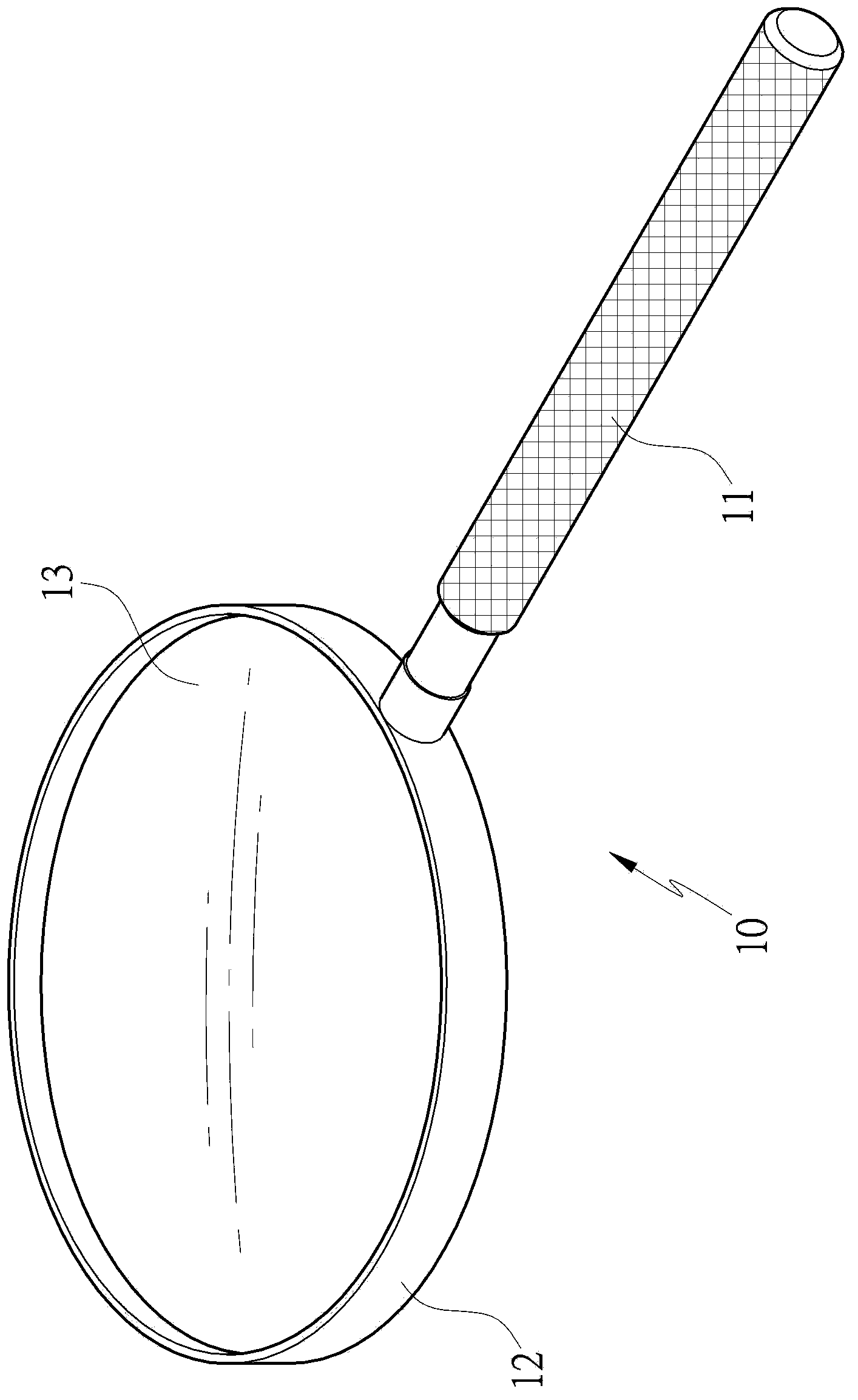
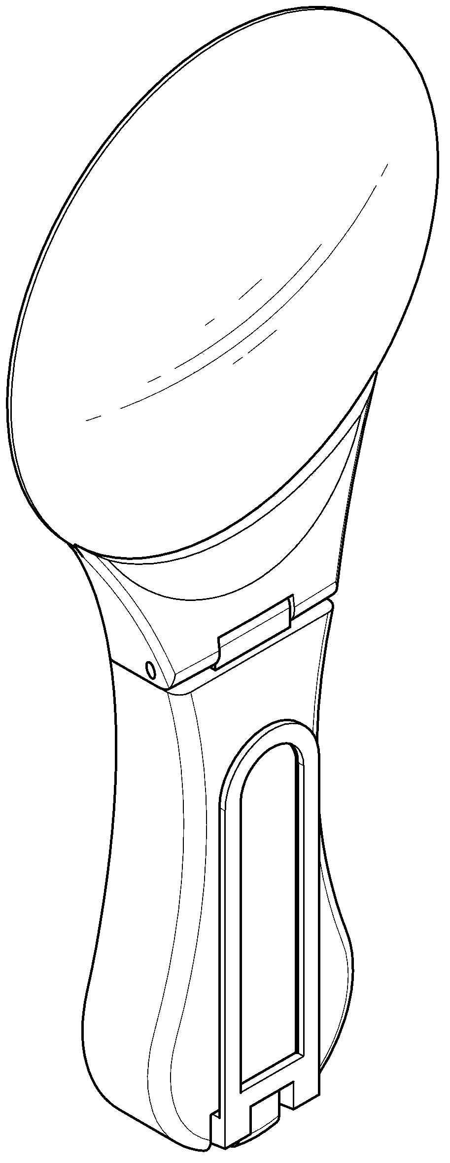
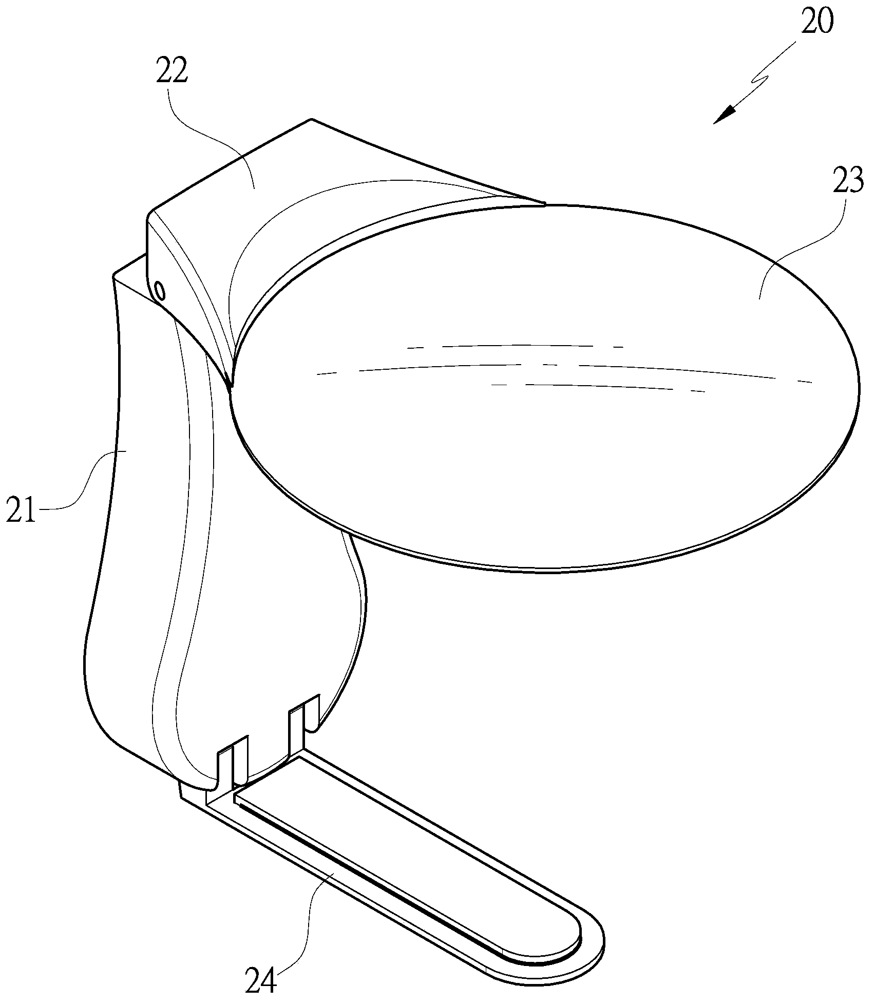
[0047] see Figure 5 , Image 6 , Figure 7 As shown, the magnifying glass device 30 of the present invention includes a grip body 31, a bearing seat 32, a foot seat 33 and a positioning member 34; one end of the grip body 31 is connected with a shaft 311 to pivotally set the bearing seat 32, So that the bearing seat 32 can swing and displace along the shaft 311, a mirror frame 321 is provided on the bearing seat 32 for installing the lens 322; one end of the foot base 33 is provided with a pivot joint 331 for The connection is pivotally arranged at the other end of the grip body 31, and a top catch portion 332 is provided on the outer surface of the pivot portion 331; in this embodiment, the other end of the grip body 31 and the The pivot joints 331 of the feet 33 are respectively provided with shaft hole...


PUM


Abstract

The invention provides a footstand adjusting and positioning structure of a magnifying lens device. The magnifying lens device is provided with a handholding body, wherein a bearing seat provided with a lens is arranged at one end of the handholding body; a footstand is provided with a pivoting part at one end, and the pivoting part is pivoted at one end of the handholding body; a propping part is arranged on the outer side face of the pivoting part; the handholding body is fixedly arranged at one end of a positioning piece, and a pressing part which elastically swings is arranged at the other end of the positioning piece in an extending manner; the pressing part abuts against the propping part of the footstand so that the pivoting position of the footstand is adjusted and positioned; therefore, the propping part of the footstand is in contact with and abuts against the pressing part of the positioning piece when the pivoting position of the footstand is adjusted, and the footstand can be actually positioned; furthermore, in a footstand pivoting process, knocking phenomena and sounds can be avoided so that the practical benefits of improving the utilization convenience and prolonging the service life are realized.

Description

technical field [0001] The invention relates to a pivot position of a positioning foot that can be adjusted arbitrarily, and the foot can be positioned accurately, and in the process of pivoting the foot, the impact phenomenon and sound can be avoided, so as to improve the convenience of use and the service life The foot seat of the magnifying glass device adjusts the positioning structure. Background technique [0002] Ordinary people often use a magnifying glass as an auxiliary tool for vision, and use the magnifying glass to magnify the refraction of light to see clearly some tiny objects and words on newspapers and magazines; please refer to figure 1 As shown, it is an existing magnifying glass 10 in the market. The magnifying glass 10 is provided with a handle 11, and one end of the handle 11 is provided with a frame 12 for installing a lens 13; Handle 11, and lens 13 is placed on tiny object and text on newspaper and magazine place, and the magnification effect of lig...

Claims


Application Information

Patent Timeline
Patent Type & Authority Applications(China)
IPC IPC(8): G02B25/00
CPCG02B25/002
Inventor 黄彦竑
Owner GEM OPTICAL
Why Eureka
Try Eureka