Check patentability & draft patents in minutes with Patsnap Eureka AI!

Water-cooled proton exchange membrane fuel cell stack and water-cooled proton exchange membrane fuel cell

A fuel cell stack and proton exchange membrane technology, applied in the field of water-cooled proton exchange membrane fuel cell stack and water-cooled proton exchange membrane fuel cell, can solve the problems of easy accumulation of water, instability, poor gas concentration, etc., and achieve gas distribution The effect of uniform, stable operation and smooth drainage

Active Publication Date: 2016-08-24
BEIJING NOWOGEN TECH CO LTD
View PDF8 Cites 0 Cited by
  • Summary
  • Abstract
  • Description
  • Claims
  • Application Information

AI Technical Summary

Problems solved by technology

[0011] The serpentine flow field is a flow channel form proposed earlier. Its outstanding advantage is that it can quickly remove the generated liquid water, but its disadvantages are also obvious. For a flow field with a relatively large area, because of its long flow channel length, There are many corners, resulting in large pressure drop and large difference in gas concentration distribution, and water is easy to accumulate at the corners, resulting in low system efficiency
Aiming at these problems of the serpentine flow field, there are many improved patents, such as patent number CN03806839, which divides the flow field into main and auxiliary flow fields. Although the problem of gas concentration difference is solved, the pressure drop is still large
[0012] The parallel flow field has the characteristics of pressure drop, the length of the flow channel is short, and the gas concentration difference is small, but the slight difference in the flow and reaction of the gas in the flow channel will disturb the overall performance of the battery, and it is prone to unstable performance
[0013] Therefore, it is necessary to solve the problem of uniform gas distribution, water blocking and unstable performance of the stack under low-voltage operating conditions

Method used


Image

  • Water-cooled proton exchange membrane fuel cell stack and water-cooled proton exchange membrane fuel cell
  • Water-cooled proton exchange membrane fuel cell stack and water-cooled proton exchange membrane fuel cell
  • Water-cooled proton exchange membrane fuel cell stack and water-cooled proton exchange membrane fuel cell

Examples


Embodiment Construction

[0045] The water-cooled proton exchange membrane fuel cell stack assembly of the present invention will be described below by way of example with reference to the accompanying drawings. However, it should be understood that the following embodiments and drawings are illustrative only and do not limit the scope of the present invention. The scope of the invention should be defined by the appended claims. Also, for the sake of clarity, the figures are not drawn to scale.

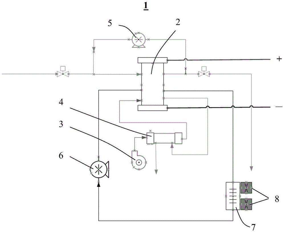
[0046] The water-cooled proton exchange membrane fuel cell stack 100 of the present invention includes a cathode flow field 20 , an anode flow field 30 and a cooling flow field 40 .

[0047] Cathode flow field

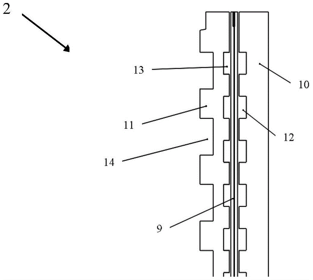
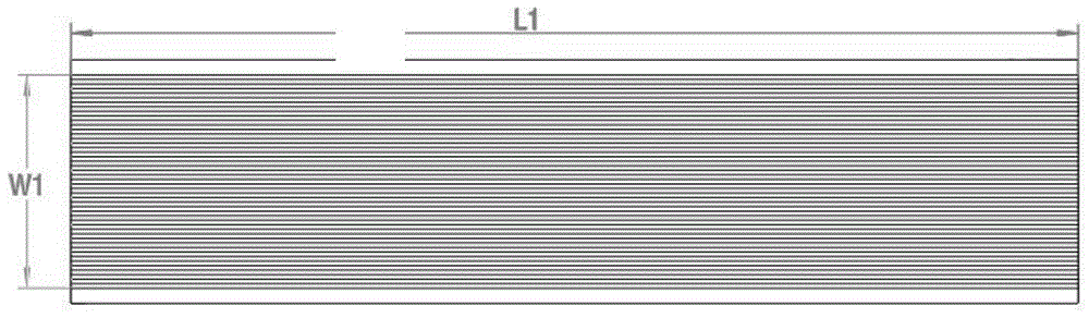
[0048] image 3 A schematic diagram of the cathode flow field of the water-cooled proton exchange membrane fuel cell stack of the present invention is shown. Figure 4 show image 3 A partial perspective view of the flow channels of the cathode flow field.

[0049] Such as image 3 As shown, t...


PUM


Abstract

The invention relates to a water-cooled proton exchange membrane fuel cell stack and a water-cooled proton exchange membrane fuel cell including the stack. The stack includes: a cathode flow field, which is a parallel flow field and has an inlet and an outlet. The cathode flow field is placed vertically, and the direction of the flow channel is from left to right or from right to left; the anode flow field is a horizontal serpentine flow. The anode flow field is placed vertically, the entrance of the anode flow field is above the exit of the anode flow field, the entrance of the anode flow field is close to the exit of the cathode flow field, and the exit of the anode flow field is close to the entrance of the cathode flow field; The cooling flow field is a vertical serpentine flow field with an inlet and an outlet, the inlet of the cooling flow field is close to the outlet of the cathode flow field, and the outlet of the cooling flow field is close to the inlet of the cathode flow field. By using the parallel cathode flow field, the horizontal serpentine anode flow field and the vertical serpentine cooling flow field and adopting the arrangement of the above flow fields, the electric stack of the present invention has uniform gas distribution, smooth drainage and stable operation during operation.

Description

technical field [0001] The invention relates to the field of fuel cells, more specifically to a water-cooled proton exchange membrane fuel cell stack and a water-cooled proton exchange membrane fuel cell. Background technique [0002] figure 1 A schematic diagram of a typical water-cooled proton exchange membrane fuel cell is shown. The water-cooled proton exchange membrane fuel cell 1 includes a core component—a water-cooled stack 2 . The water-cooled proton exchange membrane fuel cell 1 is mainly divided into three circuits: the cathode circuit, the oxidant of the cathode, such as air, is generally pressurized by the fan 3 and humidified by the humidifier 4, and then sent to the water-cooled stack 2; the anode circuit, the fuel of the anode , such as hydrogen with a purity greater than 99.999%, enters the water-cooled stack 2 and circulates through the air pump 5; in the cooling circuit, the coolant, such as deionized water, circulates through the liquid pump 6 and dissi...

Claims


Application Information

Patent Timeline
Patent Type & Authority Patents(China)
IPC IPC(8): H01M8/24H01M8/04H01M2/14H01M8/026H01M8/0263H01M8/04029H01M8/2457
CPCH01M8/026H01M8/0263H01M8/2465Y02E60/50
Inventor 张苹欧阳洵毛崚
Owner BEIJING NOWOGEN TECH CO LTD
Features
  • R&D
  • Intellectual Property
  • Life Sciences
  • Materials
  • Tech Scout
  • Unparalleled Data Quality
  • Higher Quality Content
  • 60% Fewer Hallucinations
Learn More