Electronic violin
A violin and electronic technology, applied in the direction of electroacoustic musical instruments, instruments, etc., can solve the problem of poor realism of playing, and achieve the effect of improving the fun of playing
- Summary
- Abstract
- Description
- Claims
- Application Information
AI Technical Summary
Problems solved by technology
Method used
Image
Examples
Embodiment 1
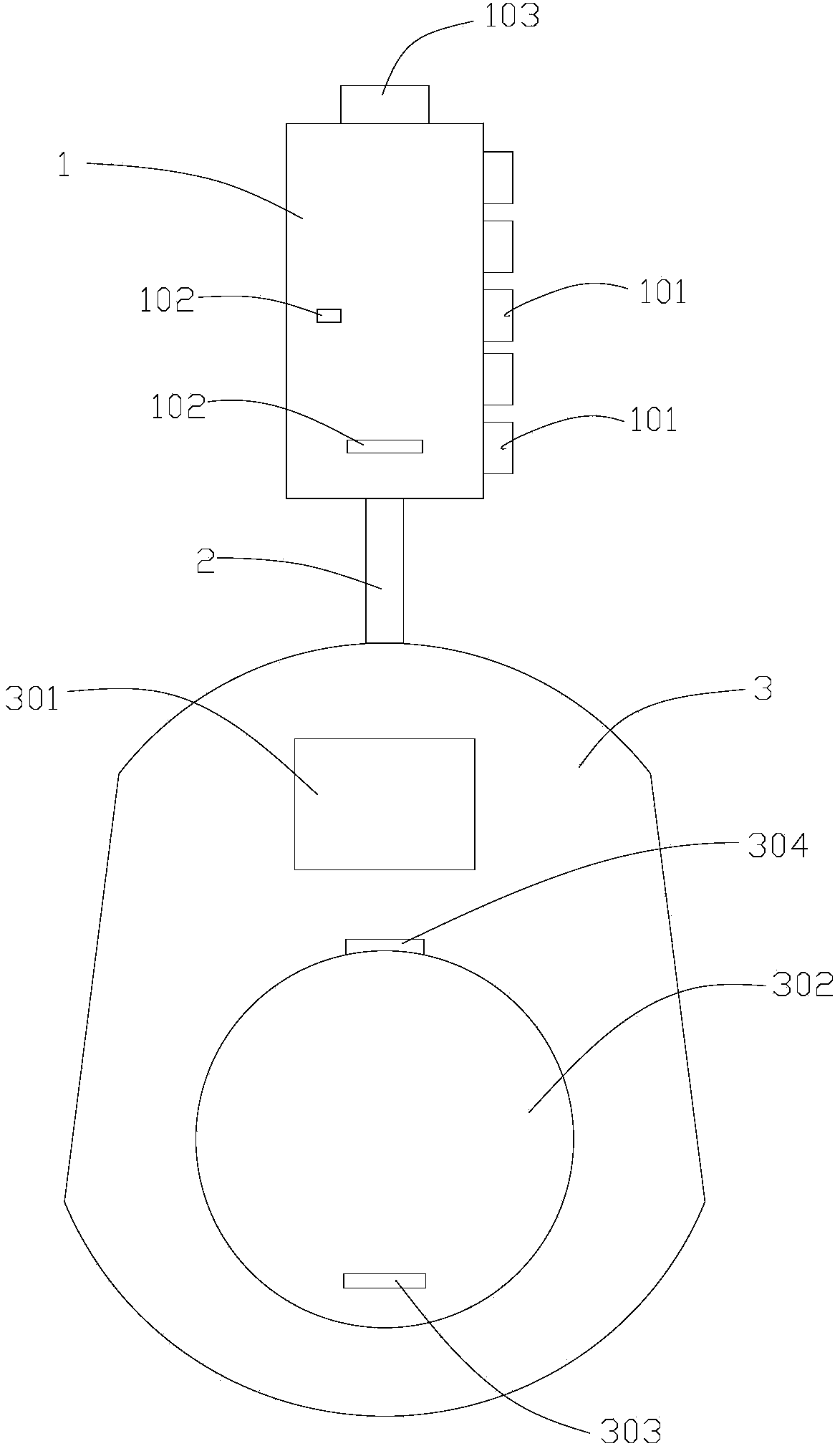
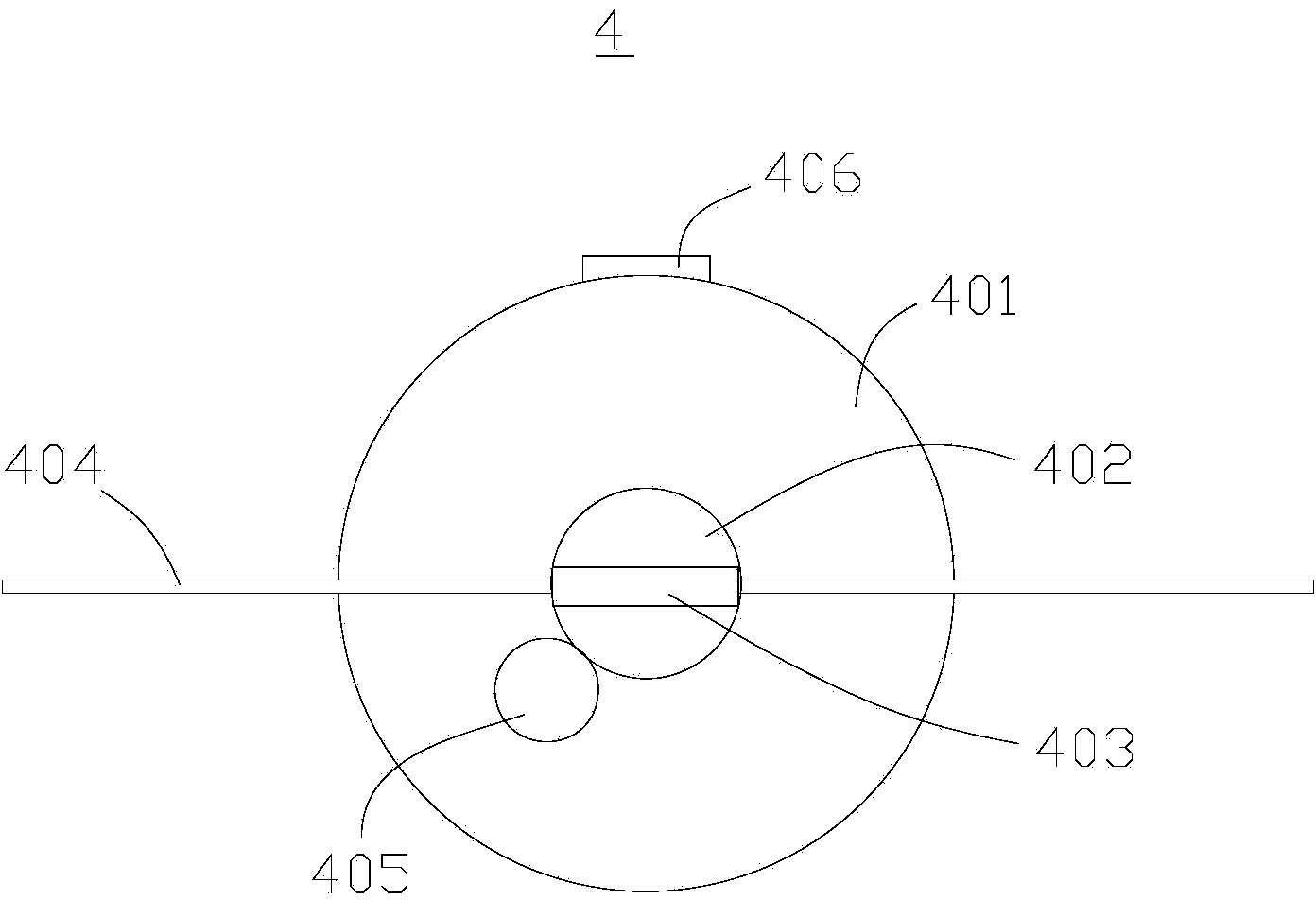
[0026] Such as figure 1 and figure 2 As shown, a kind of electronic violin of this embodiment is schematically drawn, which includes a piano head, a piano body 3 and a bowstring assembly 4 , and the piano head is connected to the piano body through a connecting rod 2 .
[0027] The headstock is provided with a display screen 1 for displaying an indicating block 102 and a plurality of string keys 101 arranged on one side of the display screen 1, each string key 101 corresponds to a position of an indicating block 102 correspond. The number of string keys 101 and indicator blocks 102 in this embodiment are five. The indication block 102 of this embodiment is consistent with that described in the Chinese invention patent application with the application number CN201410312842.0.
[0028] The piano body 3 is equipped with a main control circuit, a memory, a sound source circuit, a power amplifier and a loudspeaker, and the piano body 3 is provided with control buttons 301 and a...
Embodiment 2
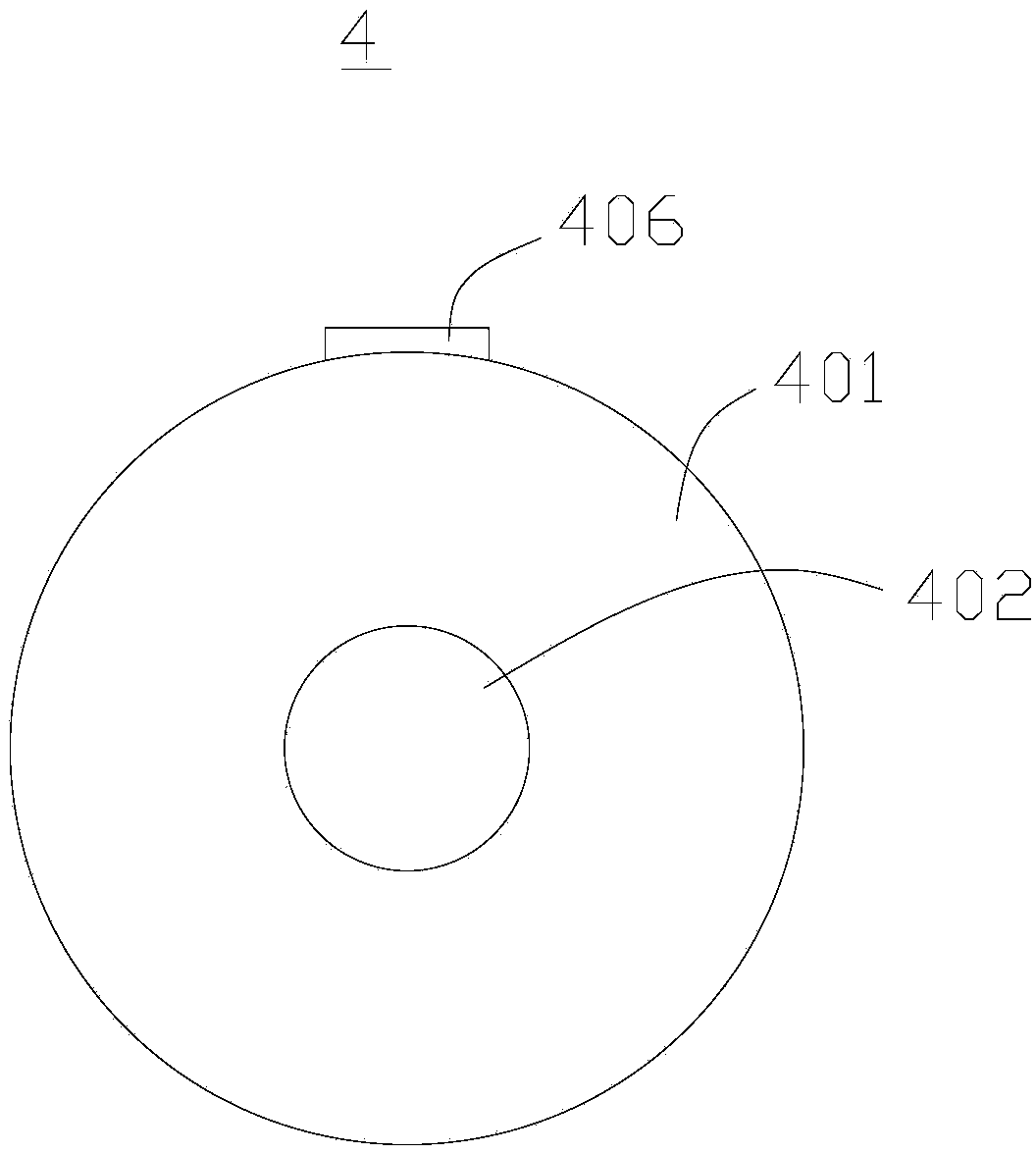
[0037] Such as image 3As shown, the difference between the present embodiment and the first embodiment lies in the different structures of the playing components. The playing assembly of the bowstring assembly 4 of the present embodiment includes a rolling ball 402 and a photosensitive assembly (not shown) for sensing the rolling change of the rolling ball 402, and the base 401 offers a groove (not shown in the figure). Out), the rolling ball 402 is installed in rolling fit with the groove, and the light sensing component is electrically connected with the connecting terminal. One side of the base 401 is also provided with a clip 406 matched with the clip slot 304 . The specific assembly structure of the rolling ball 402 and the light sensing component can be the same as the light source, lens component and sensor in the photoelectric rolling ball mouse disclosed in the Chinese utility model whose application number is 201020697403.3, that is to say, the rolling ball 402 and...
Embodiment 3
[0040] Such as Figure 4 As shown, the difference between the present embodiment and the first embodiment lies in the different structures of the playing components. The playing assembly 4 of the present embodiment comprises a rotary box 403, a rotating shaft, a pull rod 404, an infrared light generator 405, an image sensor (not shown in the figure) and a processing chip (not shown in the figure), and one end of the rotating shaft is fixed on the base 401 , the rotating box 403 is assembled on the rotating shaft and can rotate around the rotating shaft, the pull rod 404 passes through the inside of the rotating box 403 and can move along the length direction of the rotating box 403, the infrared light generator 405 is used to irradiate infrared light to the rotary box 403 and the pull rod 404, the image sensor is used to acquire the infrared light reflected by the rotary box 403 and the pull rod 404 and form an image signal, and the processor chip is used to convert the image ...
PUM
 Abstract
Description
Claims
Application Information
 - R&D
- Intellectual Property
- Life Sciences
- Materials
- Tech Scout
- Unparalleled Data Quality
- Higher Quality Content
- 60% Fewer Hallucinations
Browse by: Latest US Patents, China's latest patents, Technical Efficacy Thesaurus, Application Domain, Technology Topic, Popular Technical Reports.
© 2025 PatSnap. All rights reserved.Legal|Privacy policy|Modern Slavery Act Transparency Statement|Sitemap|About US| Contact US: help@patsnap.com


