A Disparity Vector Acquisition Method in Multi-View Video Coding

A multi-viewpoint video and disparity vector technology, which is applied in digital video signal modification, electrical components, image communication, etc., can solve the problems of inaccurate current block prediction information and affecting parallelism, etc.

Active Publication Date: 2017-07-28
HARBIN INST OF TECH
View PDF5 Cites 0 Cited by
  • Summary
  • Abstract
  • Description
  • Claims
  • Application Information

AI Technical Summary

Problems solved by technology

[0015] The purpose of the present invention is to solve the problem that the prior art relies on the spatial adjacent blocks of the current block in the current frame, which affects the parallelism in the encoding process and the obtained prediction information of the current block is not accurate enough. Disparity Vector Acquisition Method in Viewpoint Video Coding

Method used


Image

  • A Disparity Vector Acquisition Method in Multi-View Video Coding
  • A Disparity Vector Acquisition Method in Multi-View Video Coding
  • A Disparity Vector Acquisition Method in Multi-View Video Coding

Examples


specific Embodiment approach 1

[0031] Specific Embodiment 1: A disparity vector acquisition method in multi-view video coding in this embodiment is specifically prepared according to the following steps:

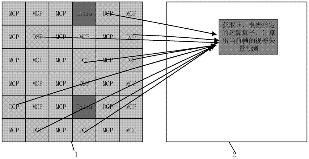
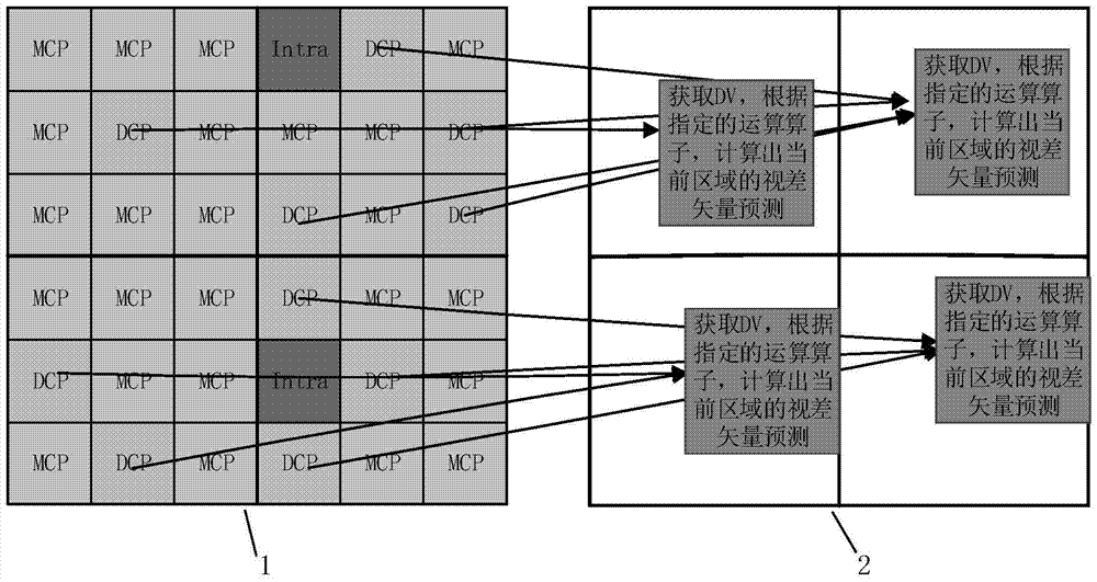
[0032] Step 1. Divide the current frame into any N parts, each part is L*W (generally ensure that both W and L are greater than or equal to 4) unit area, the unit can be square, rectangular, or other shapes, and L is the number of each part of the current frame Long, W is the width of each part of the current frame, N is an integer and N≥1, where, when N=1, as figure 2 , when N=4, such as image 3 ;

[0033] Step 2. Divide each part of the L*W unit area of ​​the current frame (when there is only one area, that is, the whole frame) into units of l*w, wherein, 4≤l≤L, 4≤w≤W;

[0034] Step 3, using the time domain reference frame to calculate the mean value, median, maximum value, minimum value or weighted average value of the disparity vector of the l*w unit to obtain the disparity vector (Disparity Vecto...

specific Embodiment approach 2

[0043] Embodiment 2: This embodiment differs from Embodiment 1 in that in step 3, the disparity vector of the l*w unit is calculated by using the time domain reference frame to calculate the mean value of the disparity vector, and the disparity vector of the L*W unit area is obtained The specific process is:

[0044] (1) Determining part of the region at the same position i as the current frame in the time-domain reference frame; wherein, i=1, 2, 3...N;

[0045] (2) Calculate the mean value of all or part of the disparity vectors of the N partial regions obtained in (1);

[0046] (3) Obtaining the mean value of the disparity vector in (2) as the disparity vector of the N part of the current frame, N=4 such as image 3 Shown; N=1 as figure 2 shown. Other steps and parameters are the same as those in Embodiment 1.

specific Embodiment approach 3

[0047] Embodiment 3: The difference between this embodiment and Embodiment 1 or 2 is that in step 3, the disparity vector of the l*w unit is obtained by the median value of the disparity vector using the time domain reference frame to obtain the disparity of the L*W unit area The specific process of vector is:

[0048] (1) Determine the i part of the area in the same position as the current frame in the time domain reference frame; where, i=1, 2, 3...N

[0049] (2) Calculate the median value of all or part of the disparity vectors of the N partial regions obtained in (1);

[0050] (3) obtain the median value of the disparity vector in (2) as the disparity vector of the N part of the current frame; N=4 as image 3 Shown; N=1 as figure 2 shown. Other steps and parameters are the same as those in Embodiment 1 or Embodiment 2.


PUM


Abstract

A disparity vector acquisition method in multi-viewpoint video coding, the invention relates to a disparity vector acquisition method. The present invention solves the problem of relying on the spatial adjacent blocks of the current block in the current frame, which affects the parallelism in the encoding process and the obtained prediction information of the current block is not accurate enough, and proposes a disparity vector acquisition in a multi-view video coding standard. method. The method is to first, divide into L*W unit area; second, divide into l*w unit; third, use the mean value, median value, maximum value, minimum value or weighted average value of the disparity vector to obtain the L*W unit The disparity vector of the region; 4. Predict the motion vector of the current block; 5. Obtain the disparity information corresponding to the inter-view reference frame; 6. Use the disparity vector of the L*W unit region obtained in step 3 to obtain the inter-view reference in the weighted mode Disparity information corresponding to the frame; 7. Get the pixel value of the current block. The invention is applied to the field of disparity vector acquisition.

Description

technical field [0001] The invention relates to a disparity vector acquisition method, in particular to a disparity vector acquisition method in multi-viewpoint video coding. Background technique [0002] In recent years, multi-viewpoint video has been favored because it can bring users a real stereoscopic experience and allow users to interactively select viewing viewpoints. However, the data volume of multi-view video is very large, so it is very important to effectively compress multi-view video. To this end, the international video standardization organization MPEG and ITU-T VCEG are jointly developing 3D video compression standards 3D-HEVC (High Efficiency Video Coding) and 3D-AVC (Advanced Video Coding). At present, the China Digital Audio and Video Coding and Decoding Technology Standard Working Group is also working on the formulation of the 3D-AVS (Audio Video coding Standard), a multi-view video coding standard with independent intellectual property rights in Chin...

Claims


Application Information

Patent Timeline
Patent Type & Authority Patents(China)
IPC IPC(8): H04N19/597H04N19/513
Inventor 范晓鹏张娜马冀赵德斌
Owner HARBIN INST OF TECH
Why Eureka
Try Eureka